

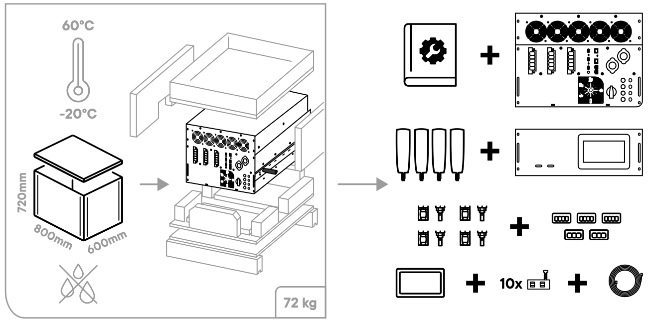
Storage and content
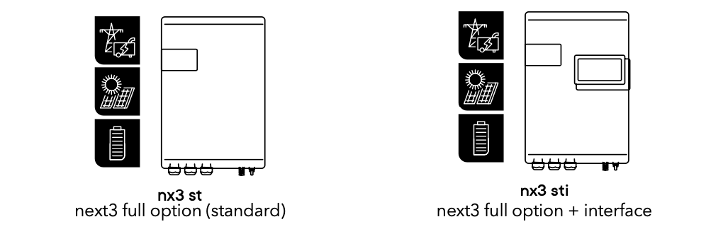
next3 wall mounted

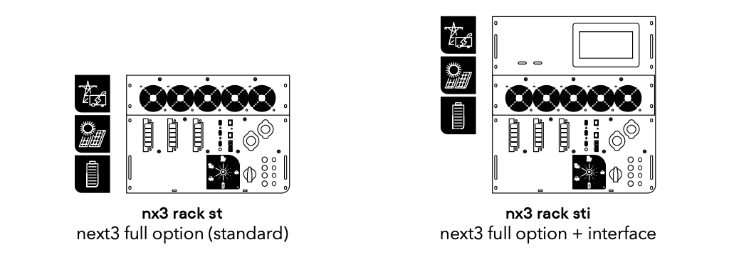
next3 rack
More information in the mounting section.
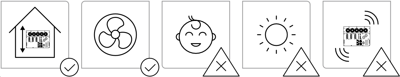
Mounting place
The next3 and batteries should only be installed by qualified personnel.
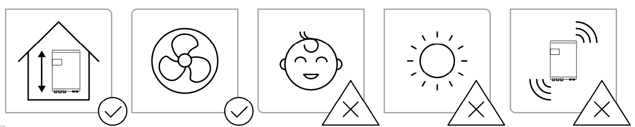
The next3 comes in IP30 with a standard coating to provide additional protection in difficult environments. We recommend installing the device in a controlled environment, limiting exposure to moisture, dust, salt, chemical, temperature changes and mechanical abrasion. The mounting location is indoors and should be protected from children and unauthorised people.
More information in the mounting section.
Fixing and dimensions
next3 wall mounted

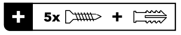
The mounting screws for fixing the mounting plate in the wall are not provided.
next3 rack version

More information in the mounting section.
Wiring
next3 wall mounted
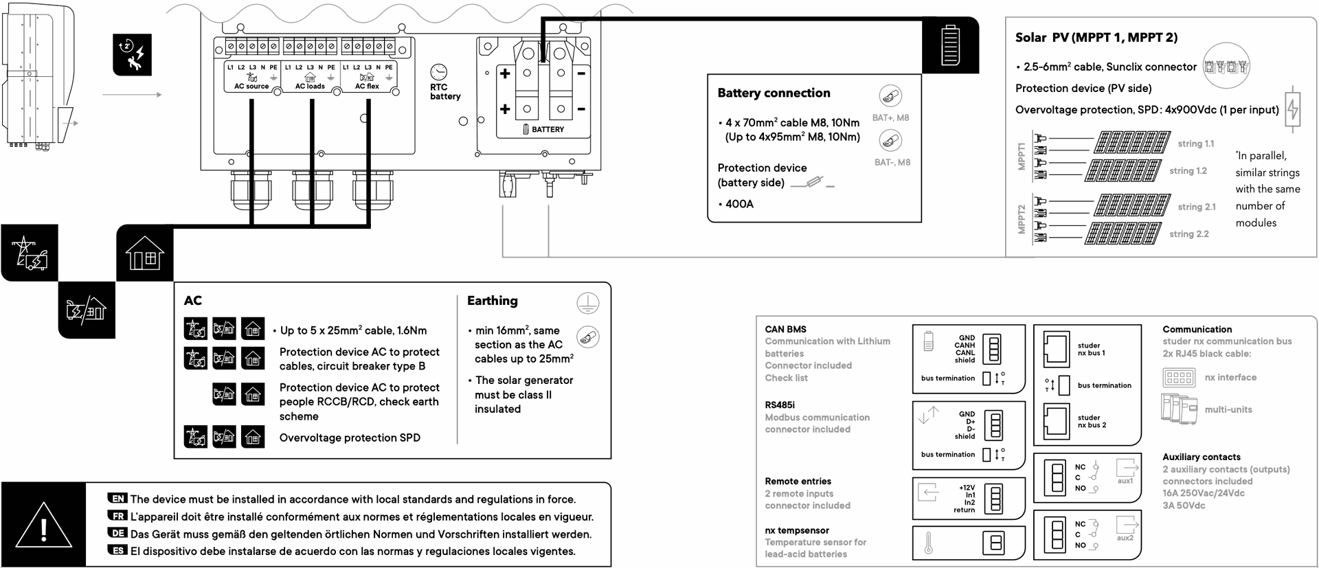
The following tools are required:

For more details about the wiring, please refer to the connection section.
next3 rack
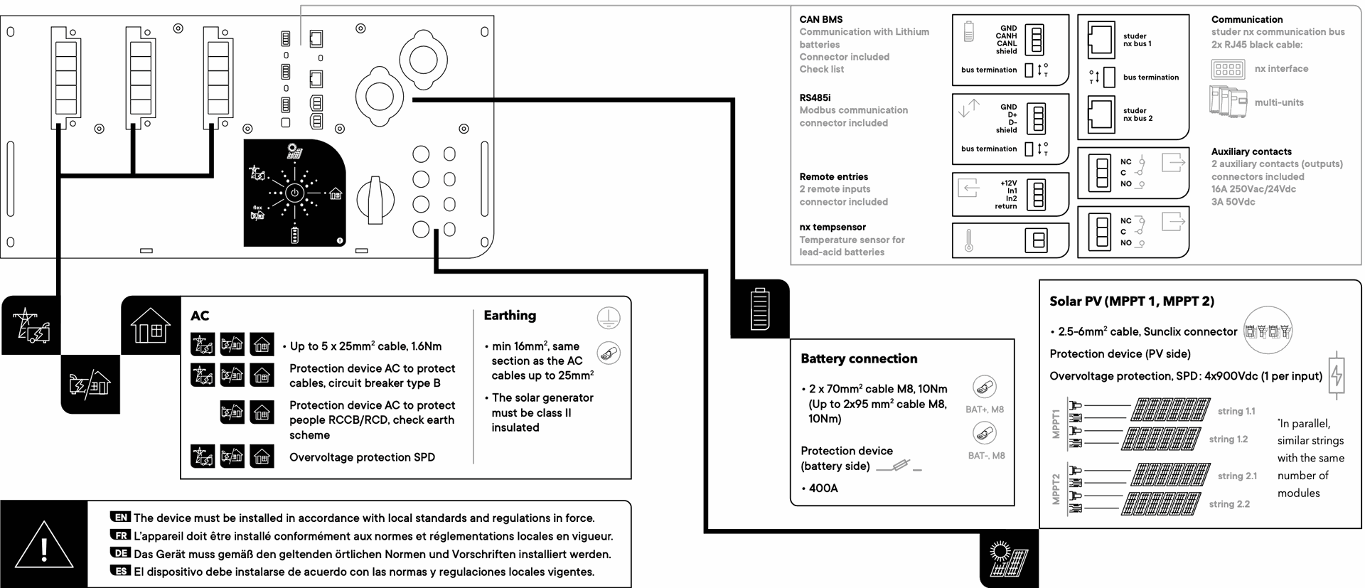
The following tools are required:
For more details about the wiring, please go to the connection section.
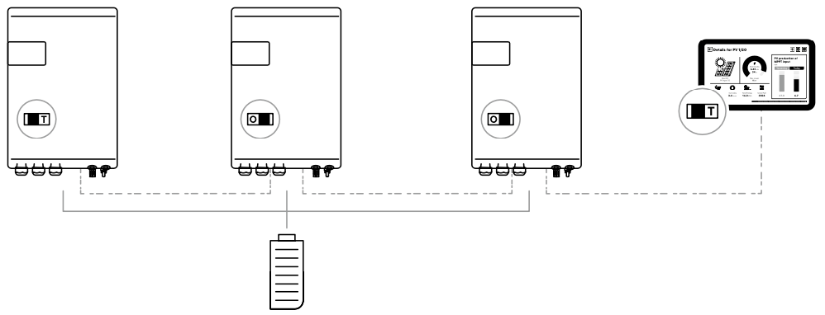
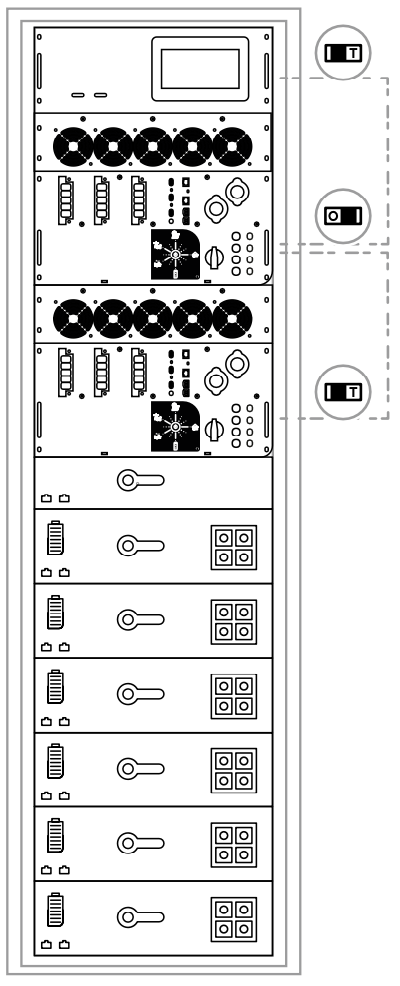
Communication and power-up
1 nx interface required in the communication bus

First start of the system
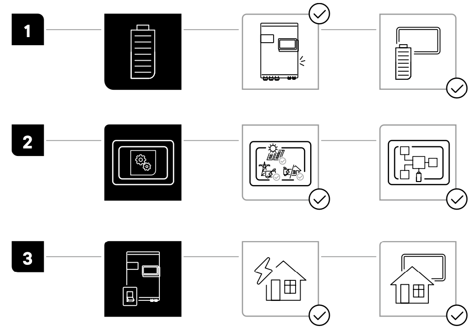
1. Start the battery, the next3 is supplied, and a beep confirms it. The nx interface is also supplied and works.
2. The first screen is the configuration wizard that will guide you through the first configuration.
3. Turn on the device using the button in the front panel or the nx interface. The AC loads are then supplied and the information is available on the screen.
More information in the power-up section.
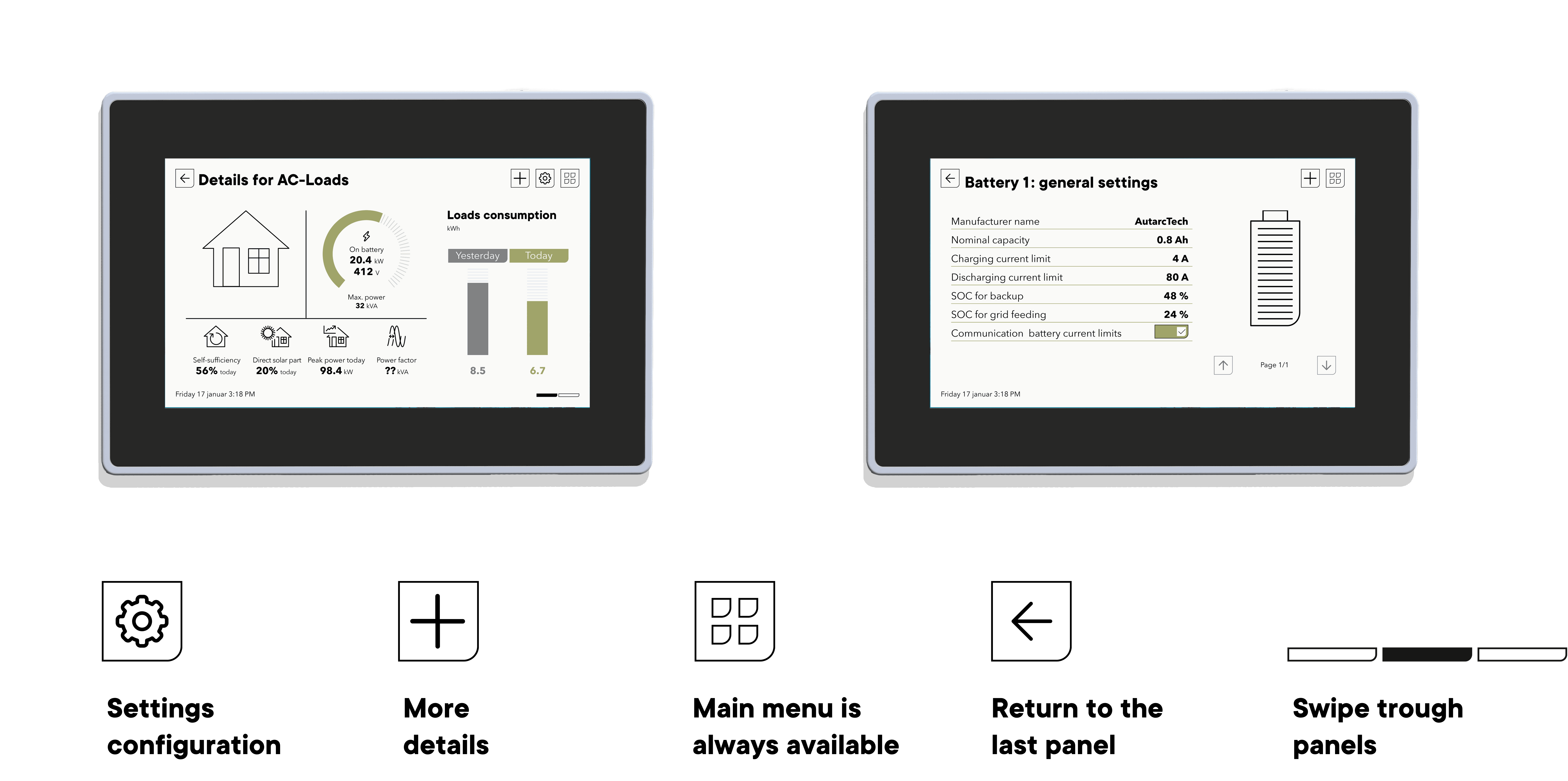
Display system
next3 wall mounted
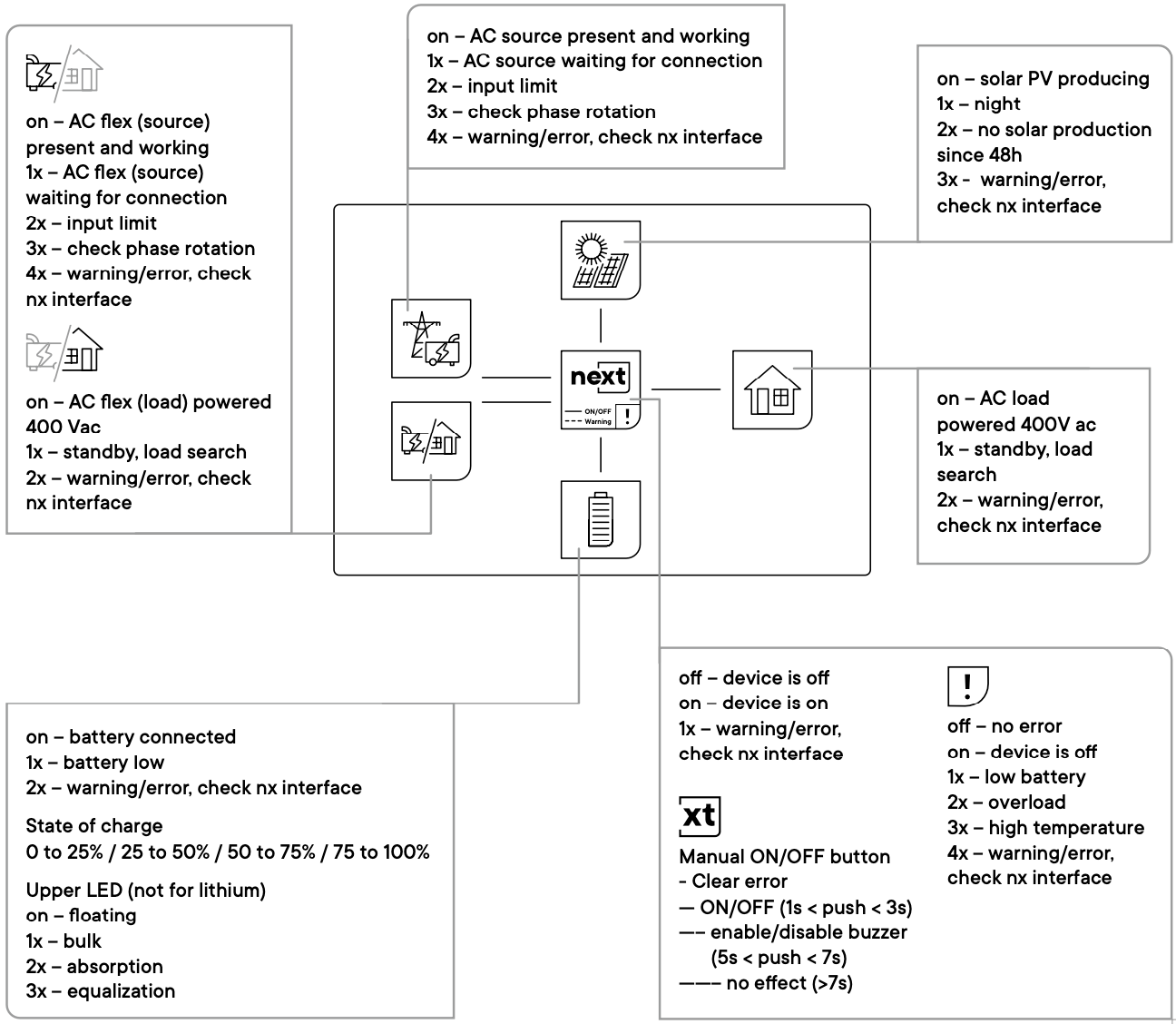
next3 rack

For more information please check the power-up section.
Configuring the next
nx interface

nextOS
The nextOS is the gate to your energy system and the platform for the graphical user interface (GUI), datalogger and monitoring. You can configure, visualise, record monitored data and be connected with the nx interface.
The configuration assistant will guide you through the commissioning of the system. Later on, you can navigate in the nextOS to visualise the system information and configure and fine tuning the installation (basic and advanced configurations).
You can click on the configuration elements for a detailed description. With nextOS the user experience is a real added value.
More information on the nextOS section.
Multi units

More information in the multi-unit application note.
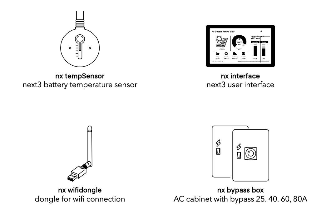
Options and accessoires
Technical data
The latest technical data can be found in the product page in our website:
next3: www.studer-innotec.com/next3
next3 rack: www.studer-innotec.com/next3-rack
Maintenance and recycling
Except for the periodic check of the connections (tightening, general condition), the next does not require any particular maintenance.
To dispose of this product, please use the service for the collection of electrical waste and observe all obligations in force in the place of purchase.