Principle
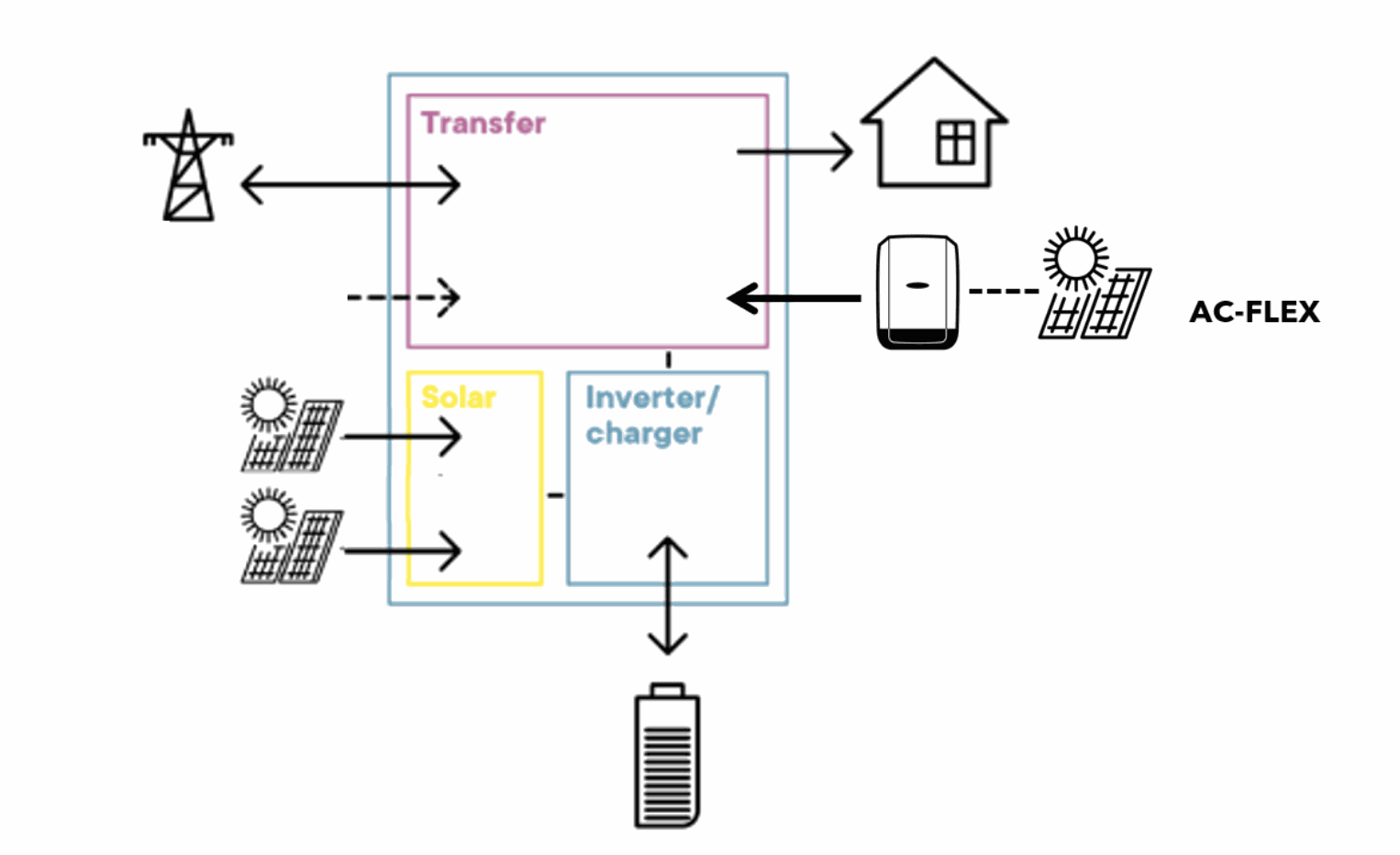
The AC-coupling is the principle of using separated battery inverters and PV inverters in the same system. The different elements are connected via the AC lines and therefore the name AC-coupling.
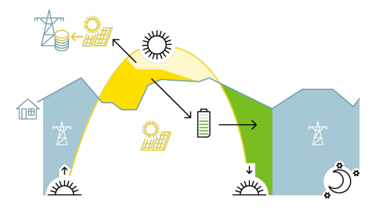
In islanded mode, the battery inverter creates the voltage/frequency of the local grid and the solar grid inverters synchronize and connect to that local grid as if they were on the normal grid. In this kind of system, the solar production is directly consumed by the AC loads. If the solar production is bigger that the loads, the excess of the power goes back to the next3 and recharges the battery. When the battery is full, the grid inverter must reduce/stop its production.
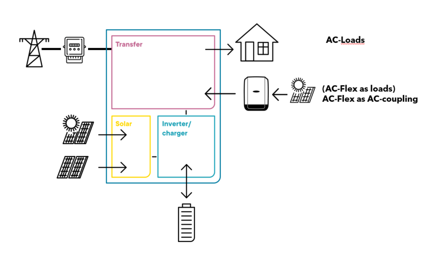
With the next3, the solar inverters are connected on the load side, either on AC-FLEX connection or AC-LOADS connection. A dedicated AC-FLEX connection is the best option because it is measured separately. That way the grid inverter has a monitoring of its full production independently of the loads and it is easier to understand what happens in the system.
The AC-coupling can be useful in various situations.
- To add solar on an existing next3 system directly in AC.
- To update an existing solar system with more solar and batteries with the use of the next3. The grid inverter is left in place and some additional solar is connected to the new next3. It is a premium choice for the case where microinverter or optimizers are used because it would be complicate to rewired the solar roof.
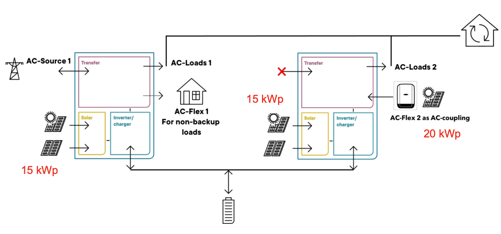
- It is also interesting for large systems, as it is not always wanted to have the full power with the backup inverter. Per example a 50kW solar system with 30kW of backup capacity would have 2 next3 in parallel and a grid inverter with up to 30kW of solar.
General system design
Studer-Innotec advises the following design rules for AC-coupling systems:
- The solar power in Ac-coupling should be smaller than the battery inverter power.
-
- For one nx3, the AC-coupled solar should be smaller or equal to 15kW.
- The grid inverter should have the modern function of power production reduction in function of the frequency of the grid to work in island mode. Else use to the simplified AC-coupling configuration.
- The battery capacity should be sufficient to absorb all the AC-coupled power.
-
- At least C/5 power with lead acid battery
- At least C/2 power with lithium battery
- For robustness of the system use a mix of AC-coupling and DC-coupling.
-
- This allows for black start of the units after an undervoltage of the battery.
- With ac-coupling, if the battery inverter is stopped, everything is stopped.
- In case of use of a genset on AC.-source instead of the grid, it is not allowed to have backfeeding to the genset. It may be causing troubles to the generator.
-
- In that case the designer must take countermeasures to avoid this. The simplest way is to disconnect the solar inverter when the genset is connected.
- The standard way to make AC-coupling is to use of the AC-FLEX connection with the proper settings. That way all the solar can be monitored automatically. This is important to understand later what happen in the system for the end user of the system.
- The next3 cannot prevent backfeeding to the grid from the grid inverter. The power coming from the AC-coupled solar inverter will directly supply the AC-loads, then the excess is used to recharge the battery until it is full but then will go straight to the grid. The next3 cannot change the frequency when it is connected to an external source.
- The energy management strategies of the next3 are identical with AC-coupling or DC-coupling.
To understand:
AC coupling with frequency shift
Concept
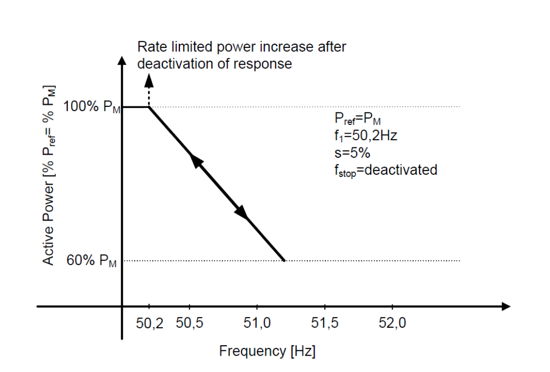
The frequency shift control uses the properties of grid inverters that must reduce the power production when the frequency of the grid increases in order to participate to the grid stability.
The frequency between 50 and 50.2Hz is used for primary control of the grid. The solar inverter must reduce linearly their power production between 50.2 and 51.5Hz.
In Offgrid mode, the next3 creates the voltage/frequency and then will modulate the frequency in function of the energy needs in the system.
Monitoring
The solar production will be correct only if the AC-coupling is done on AC-FLEX and this is specified during the wizard. In that case the AC-Flex as load connection will not be counted on the consumers loads.
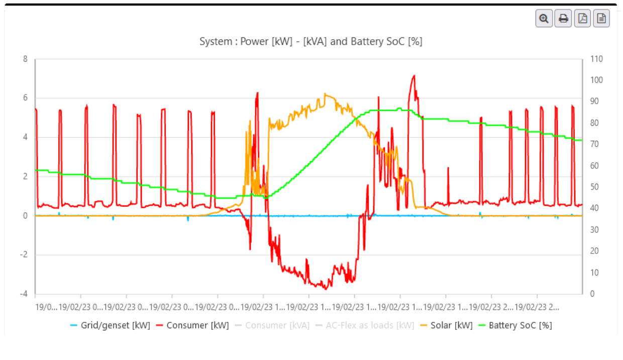
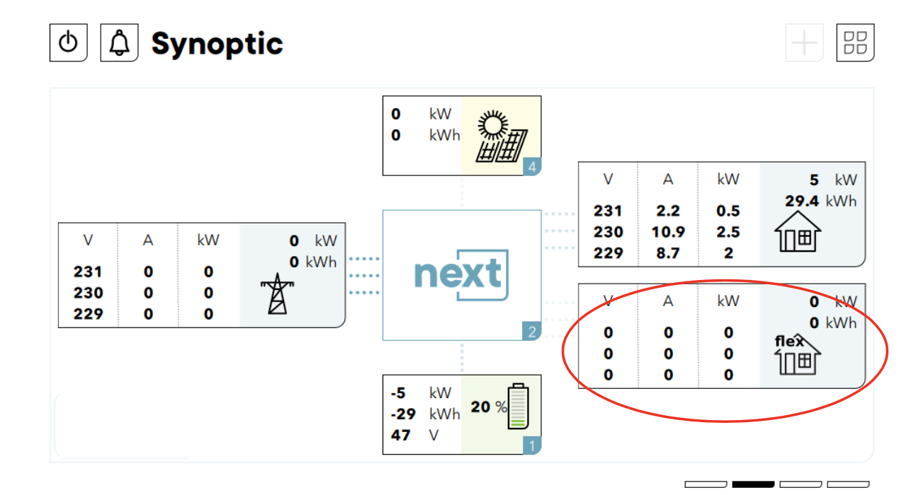
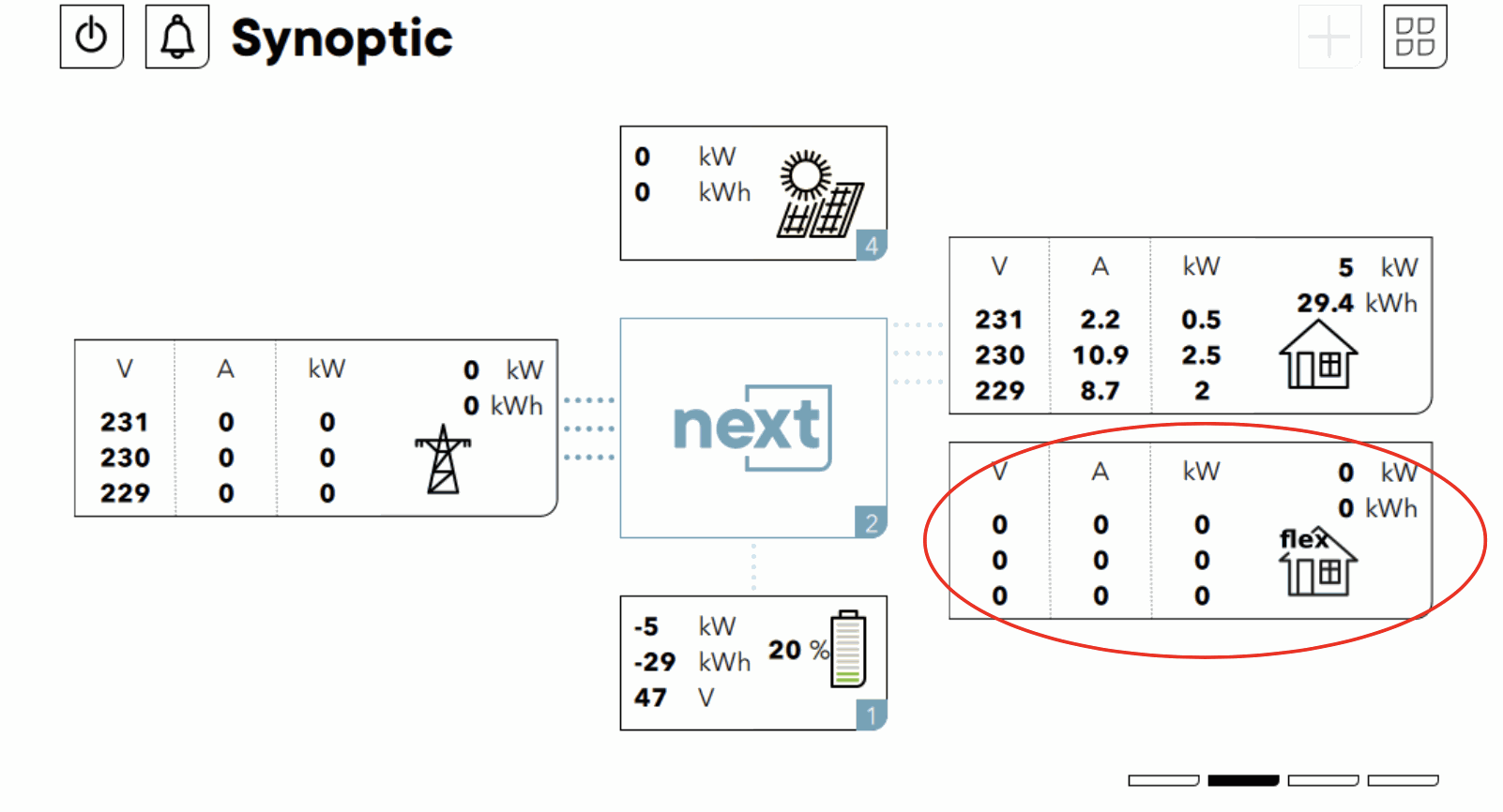
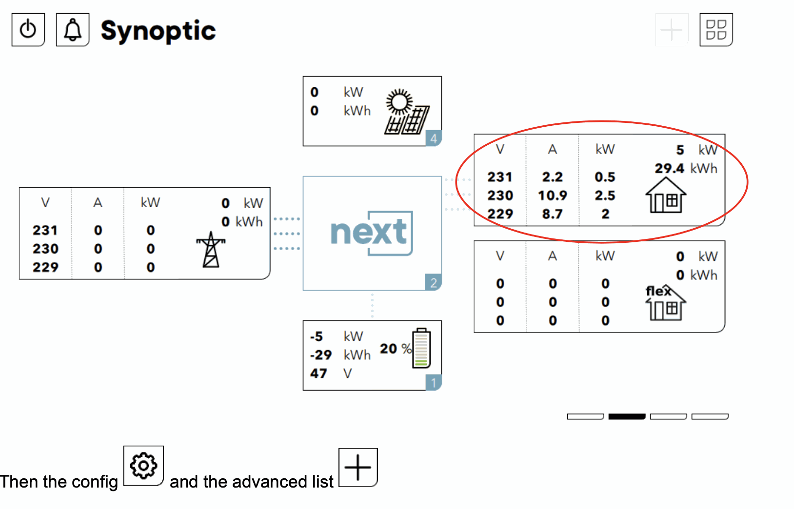
In case of connection on AC-Loads where the consumers loads and the production are directly mixed and cannot be distinguished, the excess of production will appear as a negative load on the monitoring. Example below:
Setup
The frequency control is available from software version 1.2.18.0.
With wizard
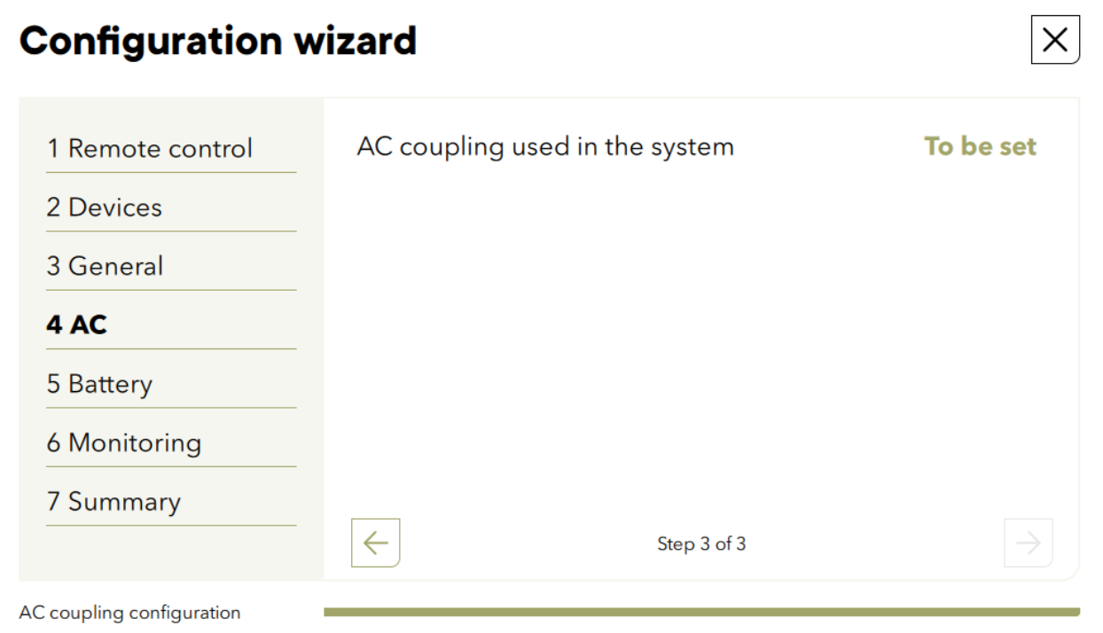
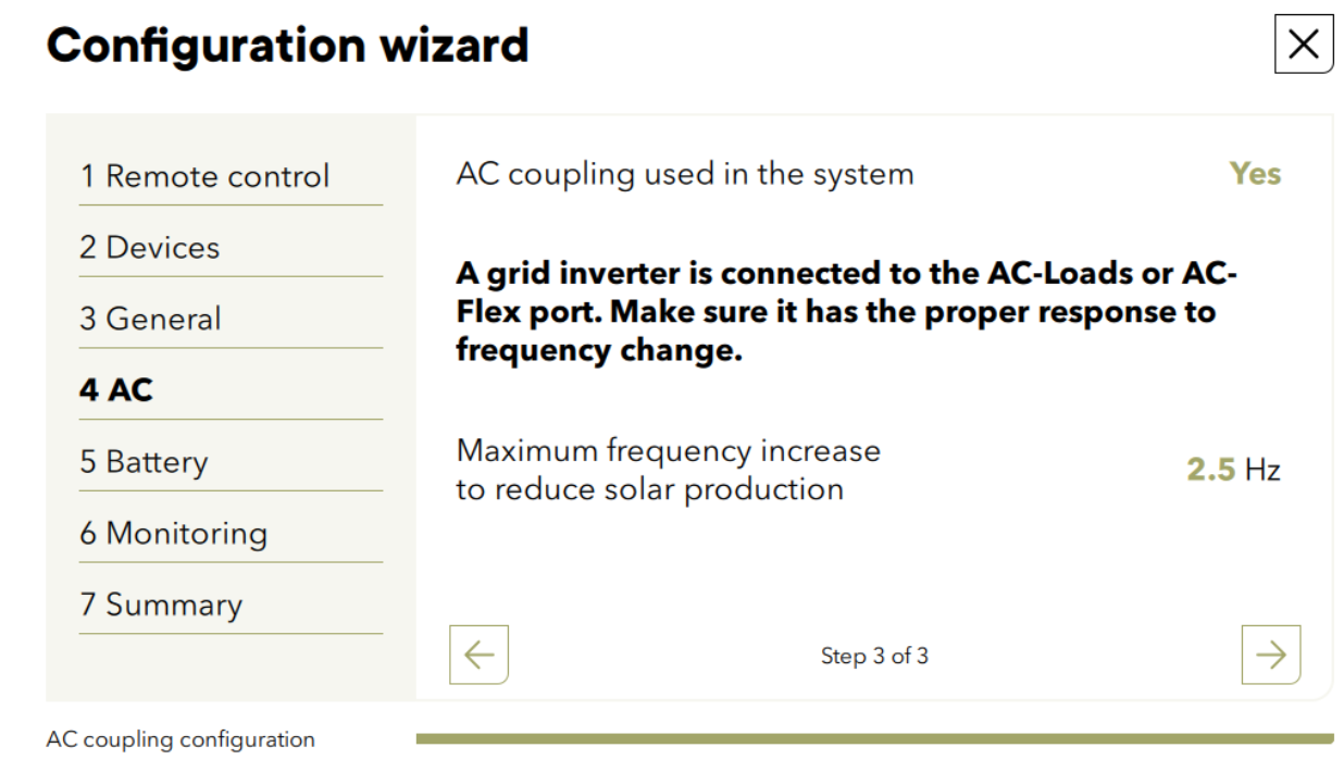
The main programming is done at the commissioning of the installation during the wizard. This is the quickest and safest way to program the system. The answer YES to the AC-coupling question will set the proper values to all the individual settings given below.
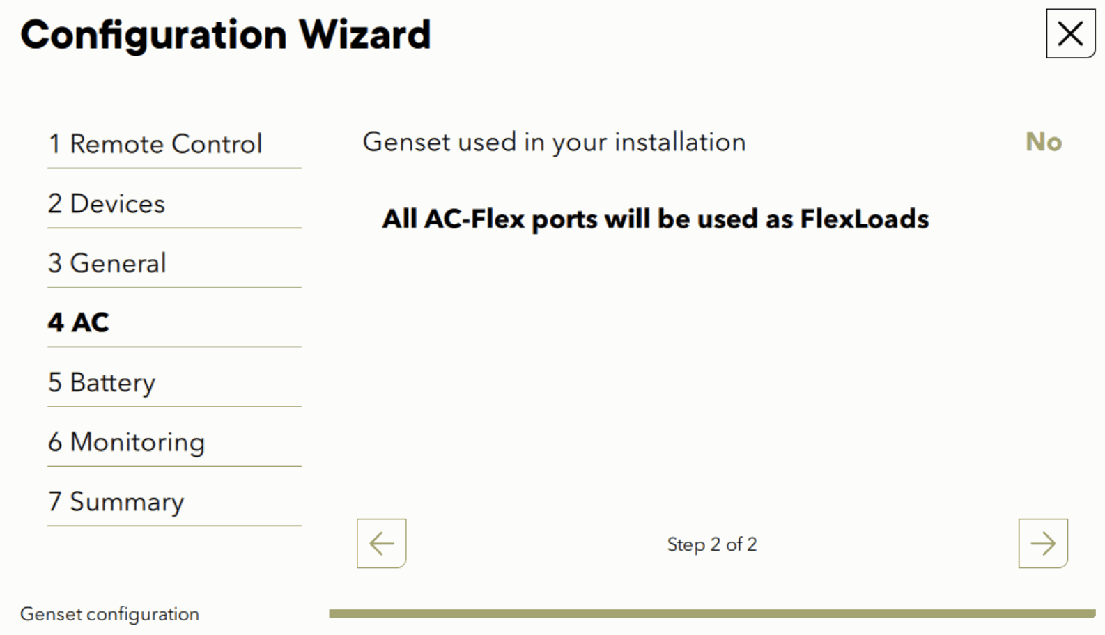
The question is asked during the AC configuration:
The max frequency increase is set by default to 2.5Hz which corresponds to today grid codes. Don’t modify it except if you have special or old grid inverters.
If the AC-coupling is connected to the AC-Flex, the relay programming to have it always connected must be done later with individual settings. If lithium batteries are used there is also special programming to do. Please read the following chapter anyway.
Directly with individual settings
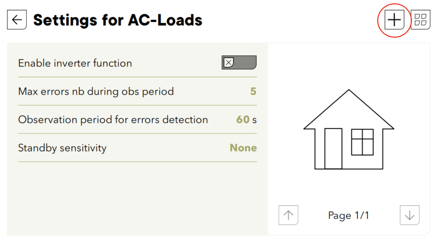
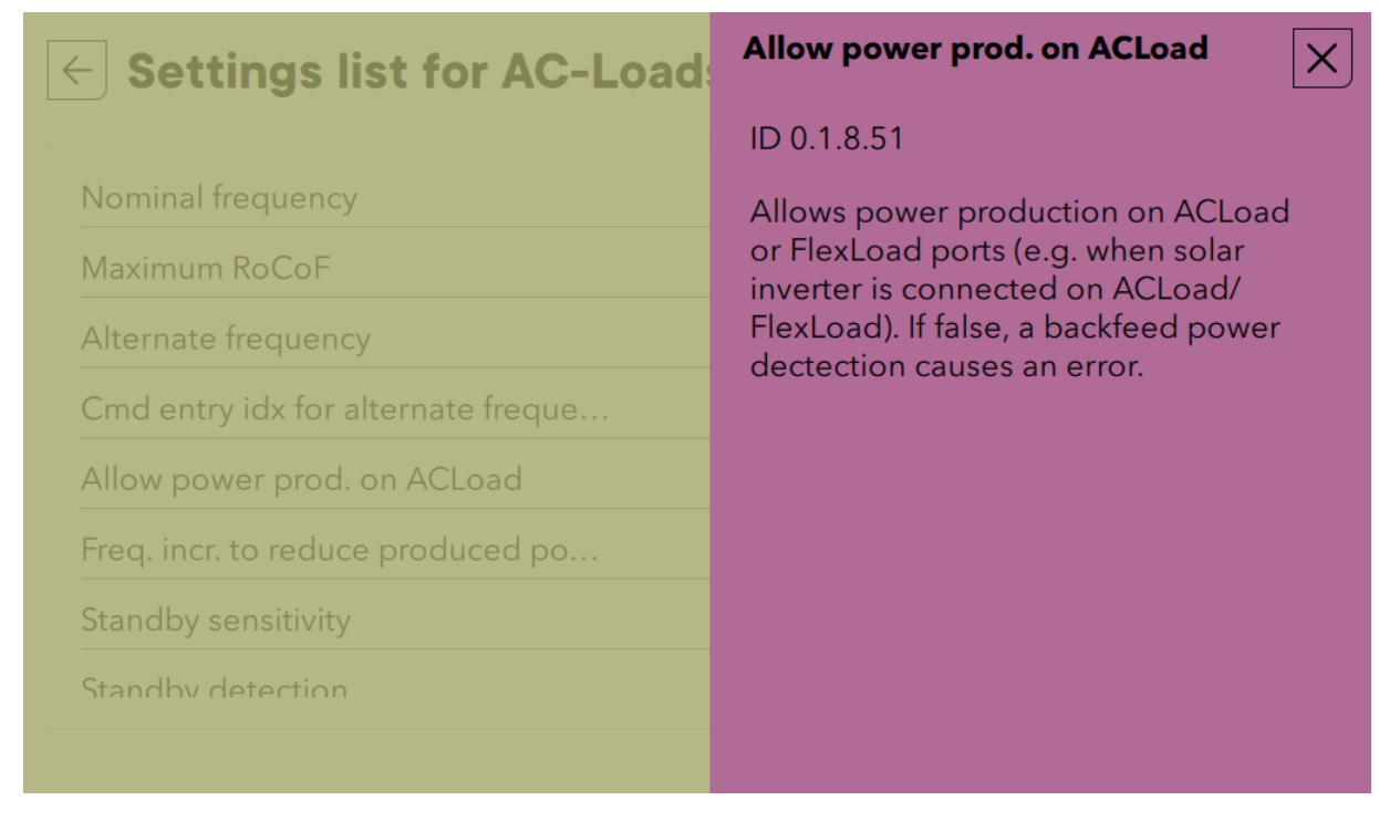
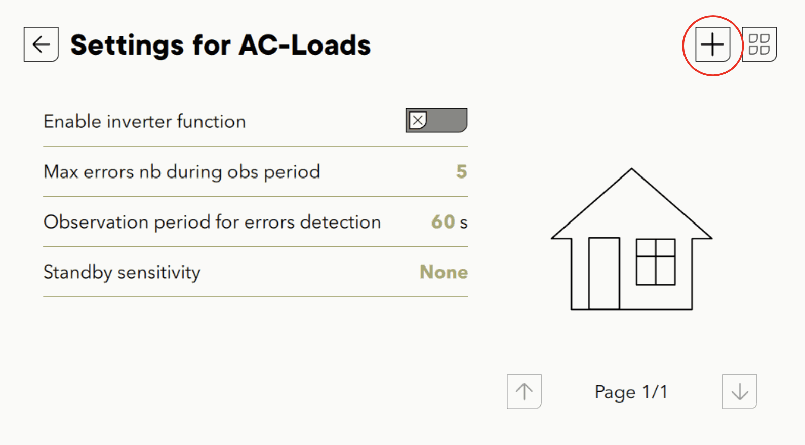
It is not a standard situation to have power coming from the AC-Load or AC-FLEX and this must be explicitly allowed with a setting, else an “back feeding” error will be raised. This is modified in the advanced settings of the AC-Loads.
Then the config and the advanced list
And find the 0.1.8.51 in the list and set to YES
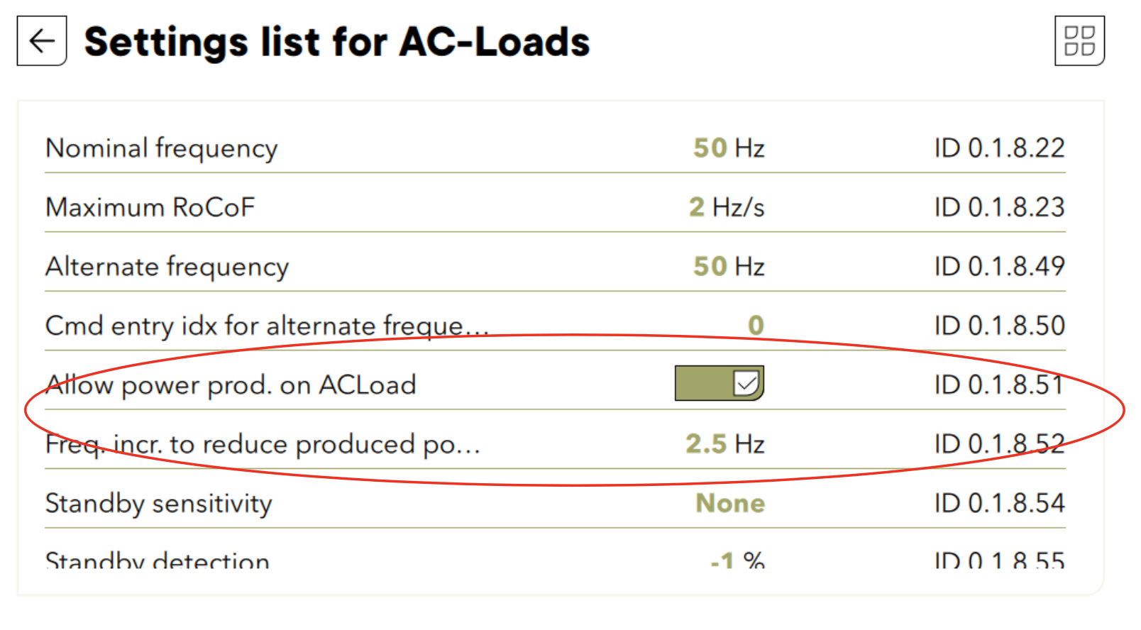
And the max frequency increase is the 1.8.52 just below. In principle 2.5Hz is already the right value. Those first two settings are set with the wizard if YES is answered to the AC-coupling question.
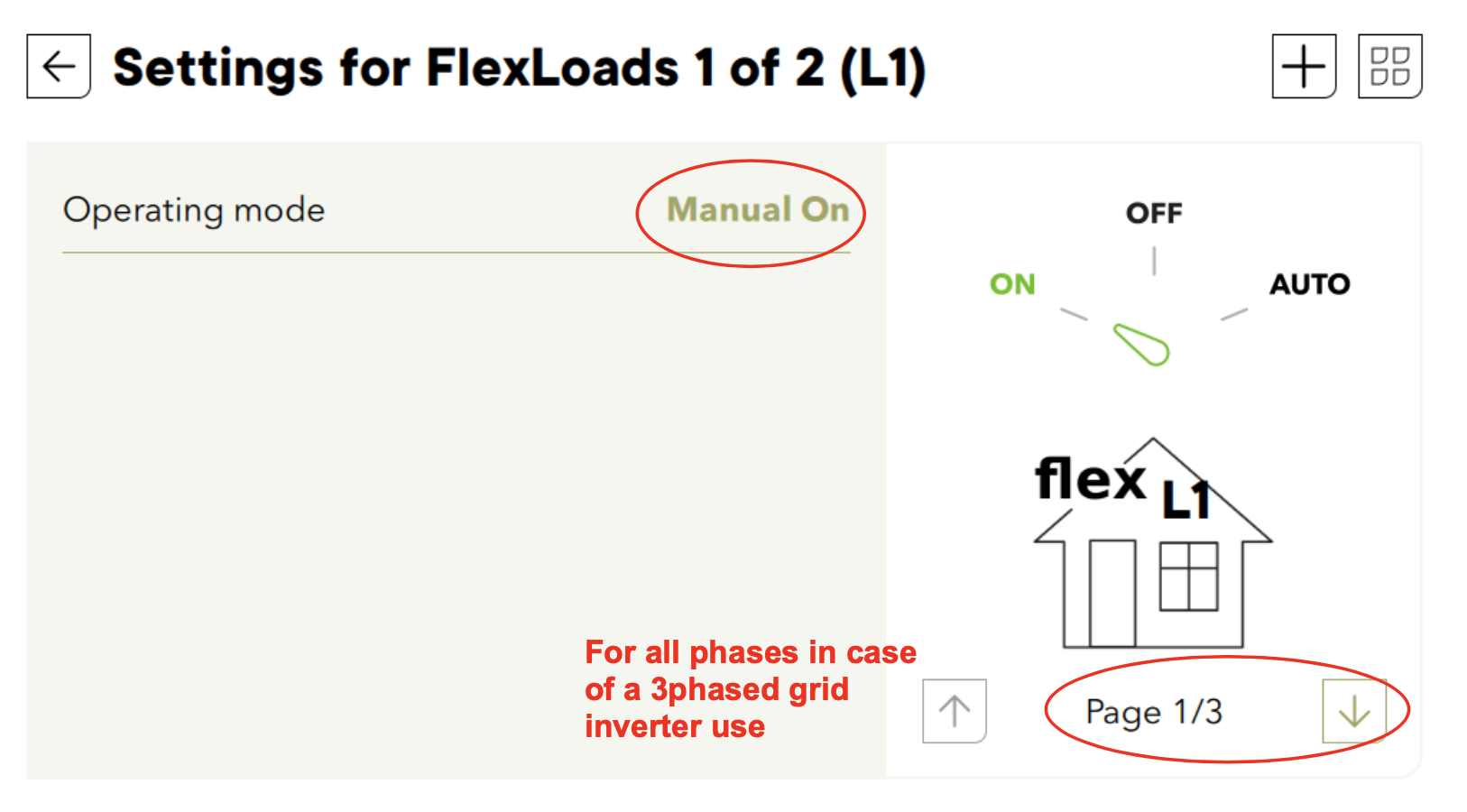
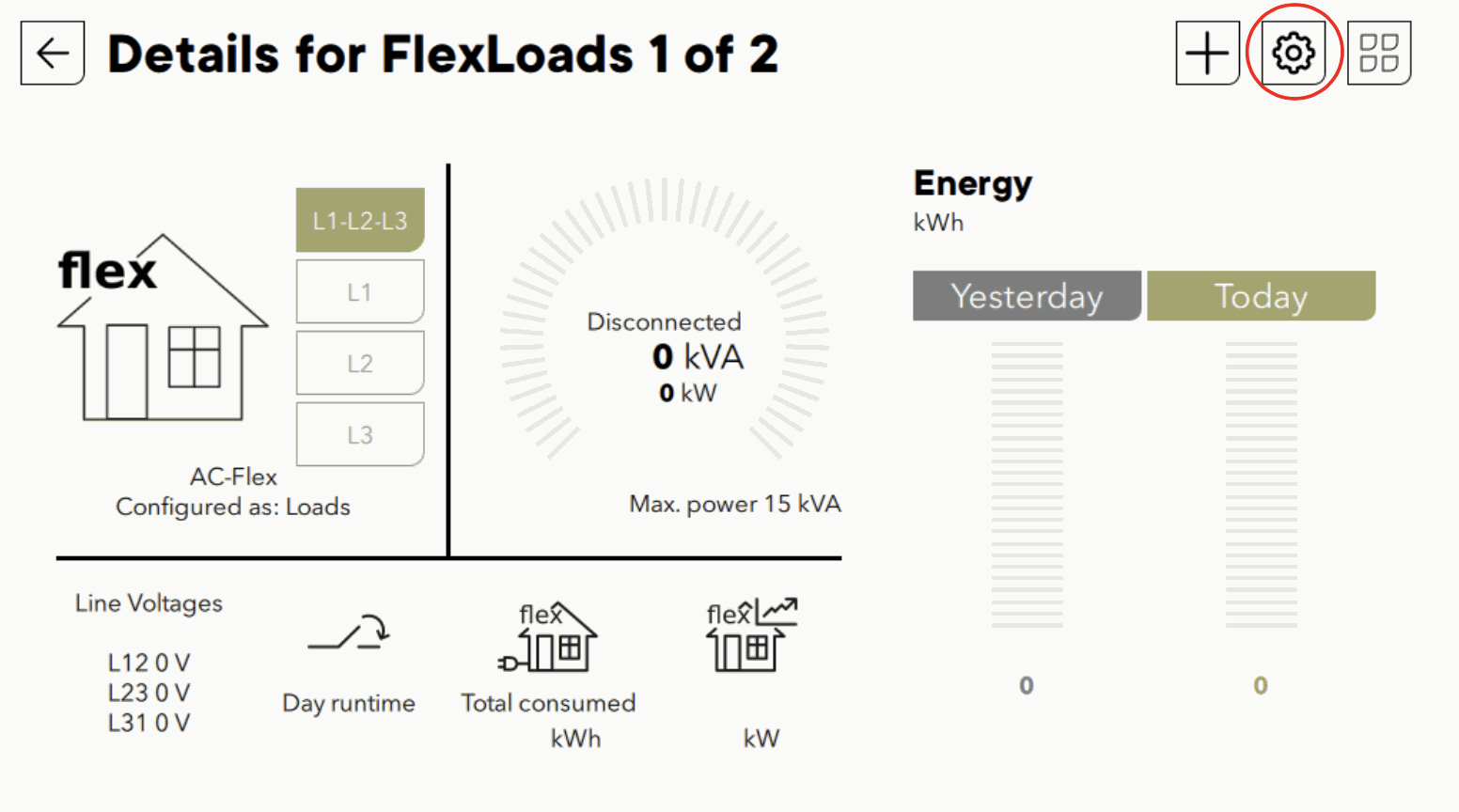
The grid inverter is connected to AC-FLEX and the relay must be always close. To program this, click on the AC-Flex part.
And in configuration
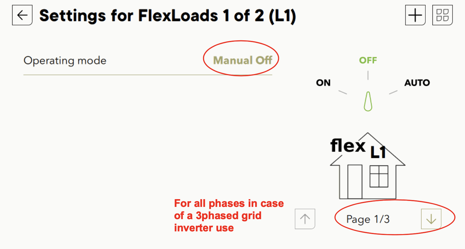
The AC-flex must be always ON for all phases:
From practice it is advised to manage the lithium battery charging a little bit differently with AC-coupling. If the battery is full, the BMS requires zero charge current and makes an error if this is not respected. In transitions from grid connected to offgrid, there is the risk to have the production of the grid inverter that is maintained for a few seconds, during the time it takes for the grid inverter to react to the increasing frequency. To limit the risk of having a battery error in that transition, Studer advises to use an charge at charge à 95% with a periodical full charge.
Simplified AC-coupling (no island mode) with AC flex
This case is for grid connected system with an existing grid inverter. A next3 can be added to increase solar quantity and add storage to the system. This works with any kind of grid inverters and there are no special requirements on the grid inverter. The unit may not be compatible with frequency shift control, that is why it must be used with grid presence only and the grid inverter is disconnected when going to island mode. This prevents unwanted/uncontrolled charging of the battery.
The connection/disconnection of the grid inverter is performed with the AC-flex relay with the proper programming given below.
Setup
The AC-Flex must be configured as a load in the configuration wizard. Answer NO to question of genset presence.
Further settings are done later in dedicated menus accessible with the EXPERT user level. Change user level in the remote menu with the code 187382.
The connection/disconnection in function of grid presence must be setup. Click on the AC-Flex part. And in configuration.
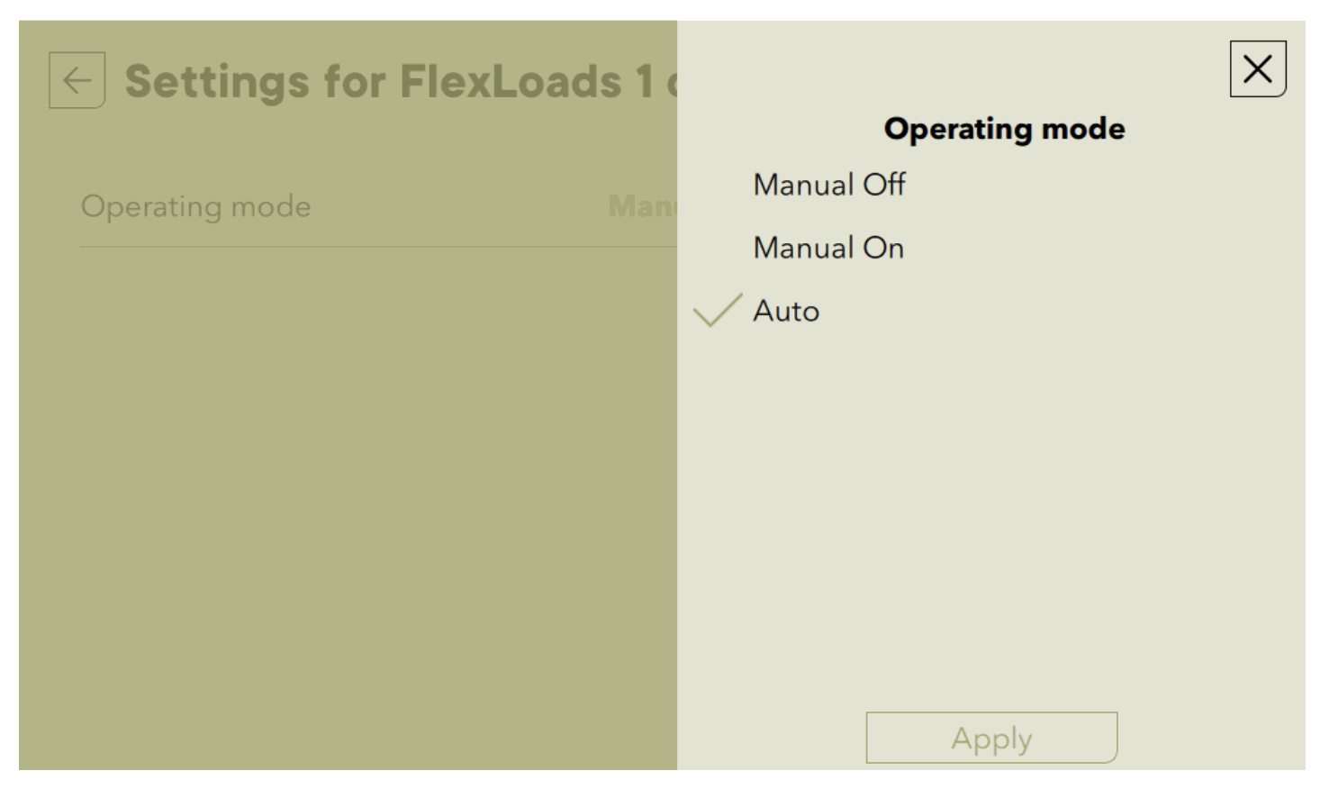
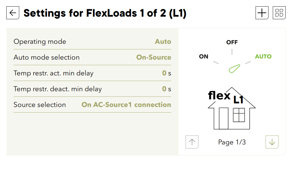
Change for each phase (for 3 phased grid inverters), the operating mode to AUTO.
And set the connection condition to “on-source”. Add a small delay of a few seconds to be sure the connection to the grid is stabilized.
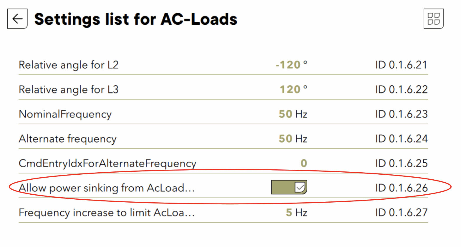
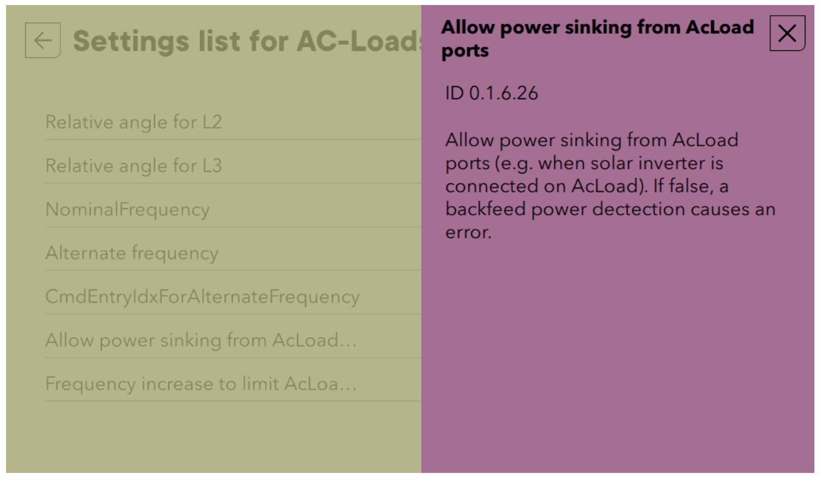
It is not a standard situation to have power coming from the AC-Load or AC-FLEX and this must be explicitly allowed with a setting, else an “back feeding” error will be raised. This is modified in the advanced settings of the AC-Loads.
And find the 0.1.6.26 in the list and set to YES.
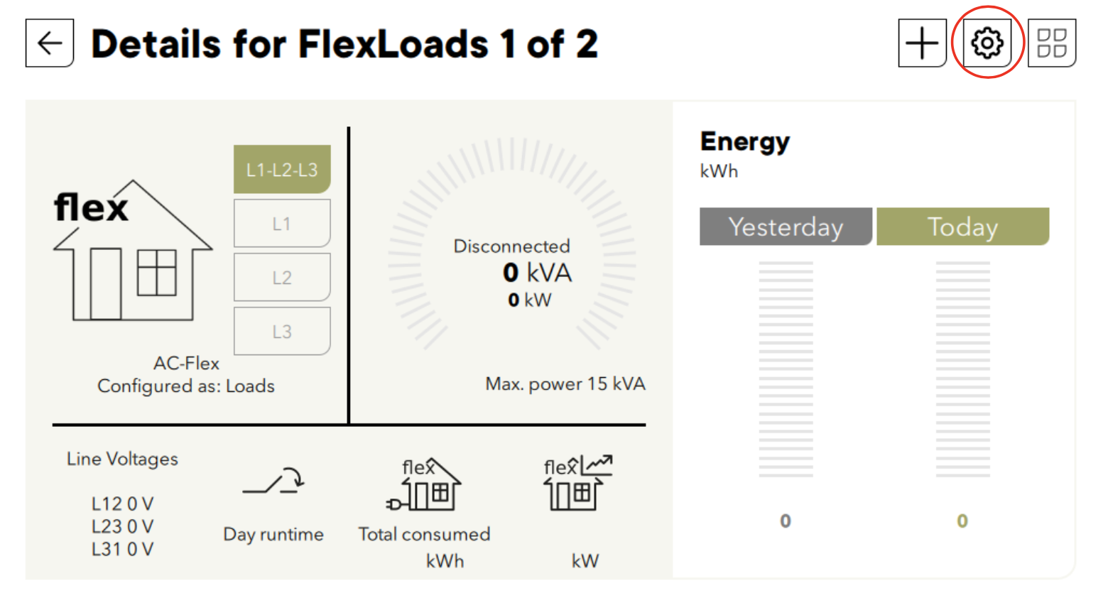
Example of use
All tests were performed at Studer factory with the Fronius Symo inverter.
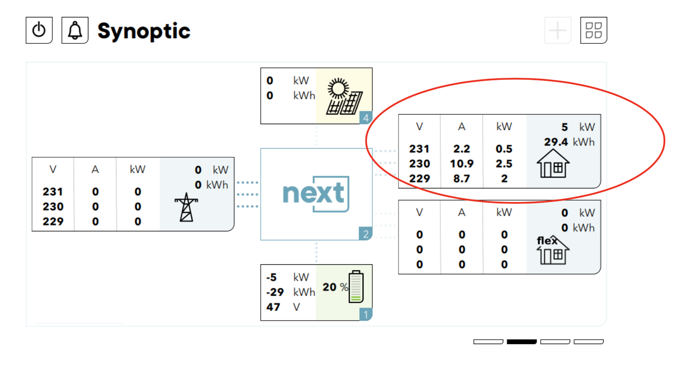
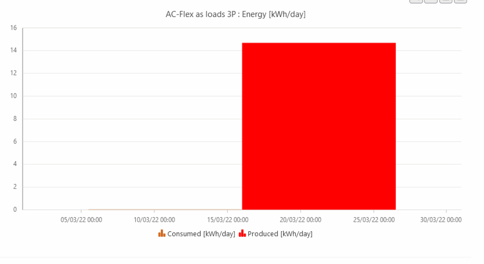
The Symo power production is monitored with the AC-flex measurement. The power flux on this connection are seen negative.
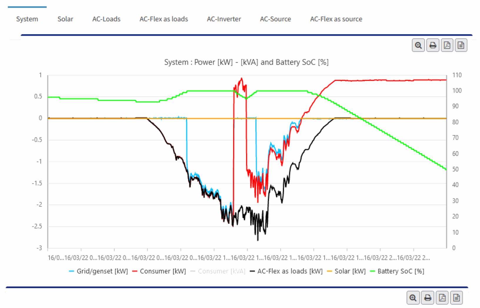
The total consumption is the sum of the AC-flex and AC-Loads. The AC-loads alone can be seen on the dedicated screen of the portal. 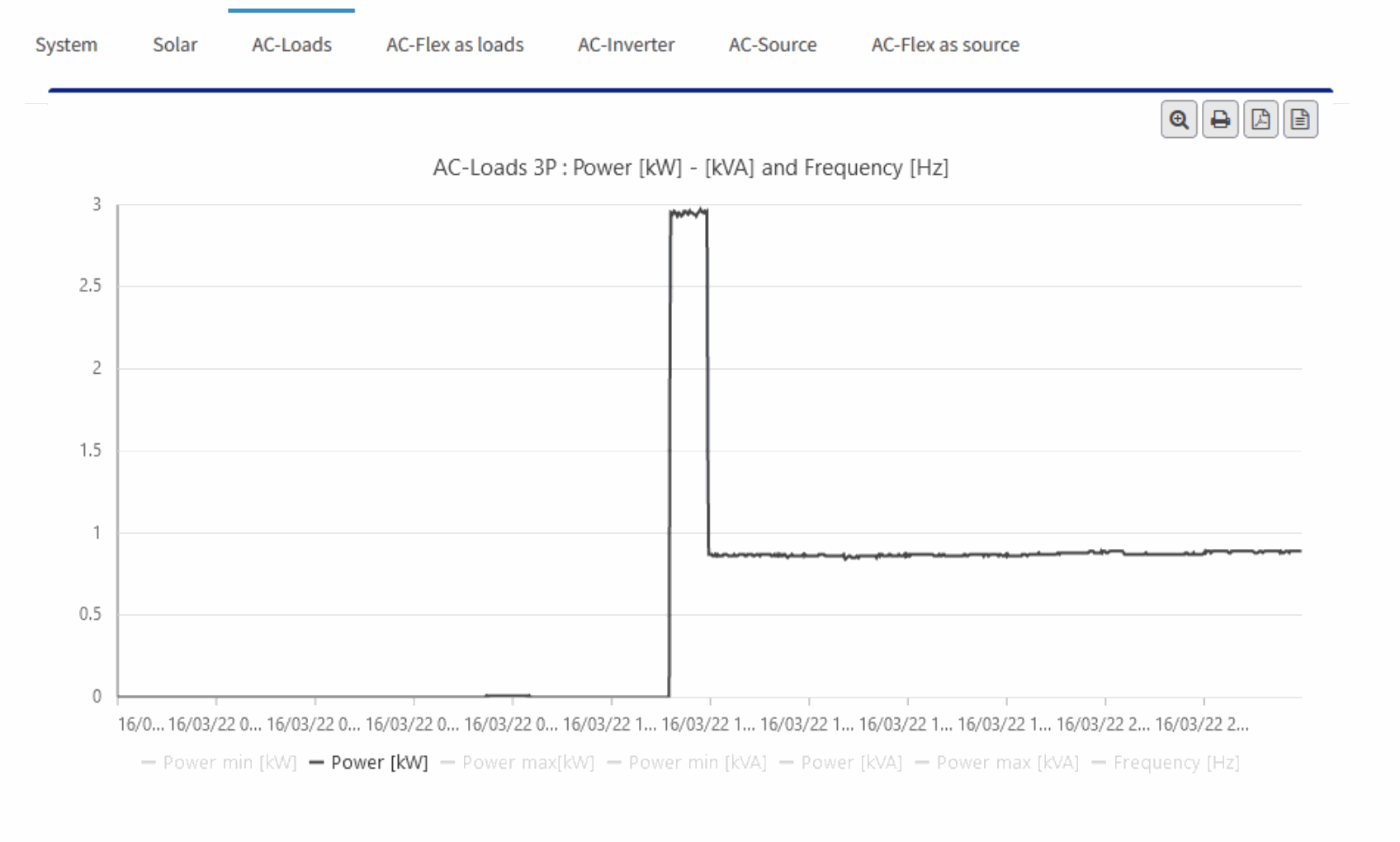
Below 3 consecutive days with solar on AC-Flex in AC-coupling and on the MPPT entry. 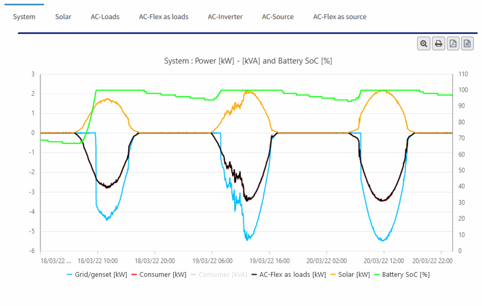
Conclusions
The simplified AC-coupling as described in this document is possible with the next3 inverter. It is a first step toward a full AC-coupling coping with all the possible situations. Some improvement for the visualization (negative powers for production coming from AC-Flex) are possible and will be added with the regular update released for the next3.