Introduction
Distribution system operators (DSO) have various requirements for the solar and storage converters connected to their grids. This is necessary for the safety of all and the stability of the electricity grids.
Network connection standards
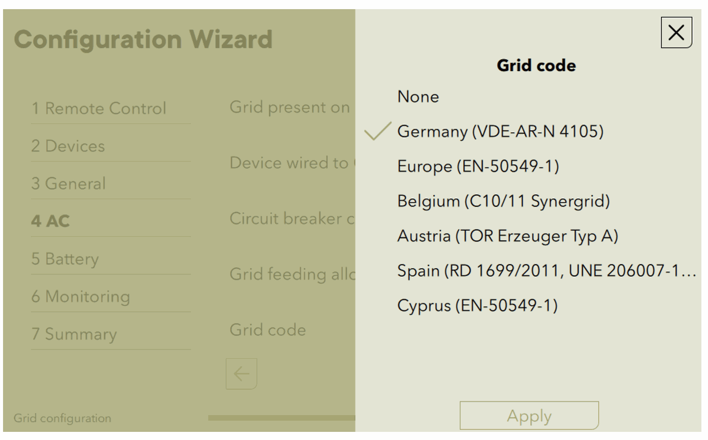
The selection of the connection standard (grid-code) must be made by the installer when commissioning the unit according to the requirements of the local DSO. The selection of the correct standard is made in one step of the setup wizard. It may no longer be changed by the end customer. Therefore, after commissioning, the next3 automatically switches to a mode in which the configuration cannot be changed. If it has to be done again, it is necessary to enter the code EXPERT/PRO, which must not be made available to the end customer.
For Switzerland, the VNB usually require the VDE-AR-N 4105. The EN50549-1 will probably be the official standard when the authorities have determined the choice. Its contents are almost identical.
Reactive power management
Feeding power into the grids causes the voltage to rise due to line impedance. This is the reverse effect of the voltage reduction at the consumers. In order to counteract local voltage increases in the grid caused by decentralised generators, the DSO can require that the devices generate reactive power.
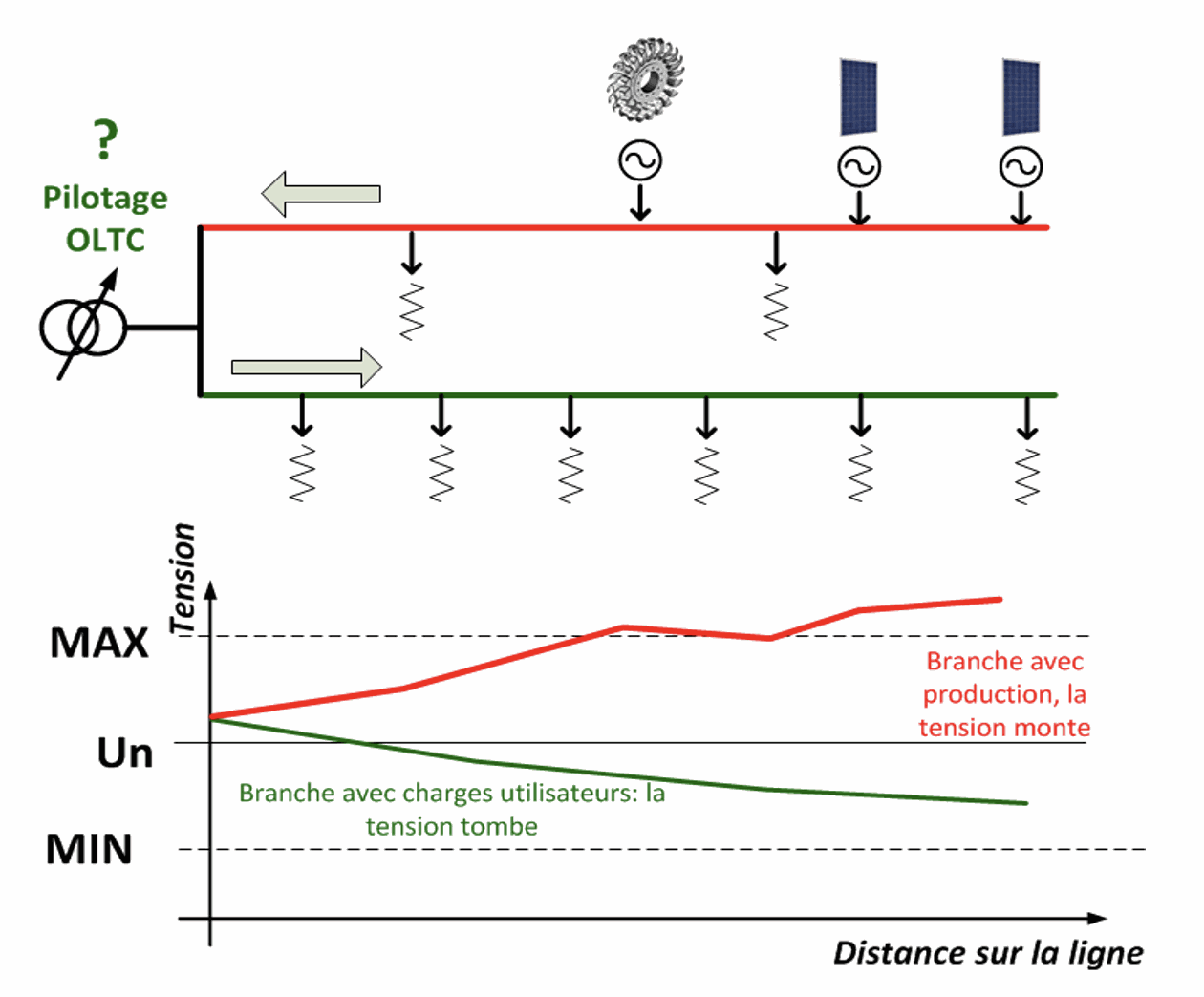
By feeding in reactive power in addition to generating energy with active power, the effect of the asset can be corrected.
Settings that are made available to the DSO
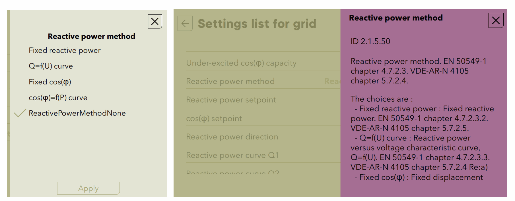
Different operating modes can be activated that manage the reagent in the next3:
- Produce at a given cos(phi) :
o Fix power
o Depending on the active power generated
- Generate reactive power depending on the voltage
- Produce reactive power directly.
Do not activate these functions without the consent of the DSO. They must be calculated by him according to the properties of the lines. Reactive production leads to losses in the next3 unit and in the lines and is not necessary in the vast majority of cases.
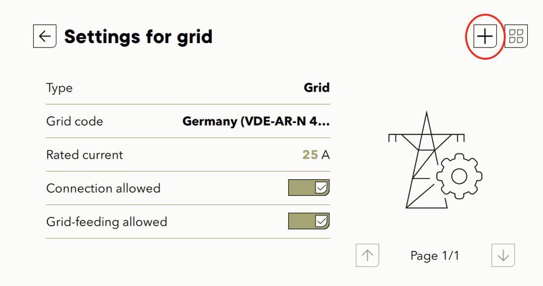
These settings are accessible in EXPERT/Professional mode. They are located in the network section on the nx interface. Use the "+" key to access the list of advanced settings.
The selection of the type of compensation by the reagent is made with parameter 2.1.5.50.
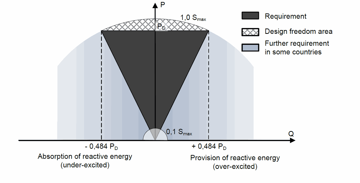
The range of maximum reactive production required by the standards is a cos(phi) of +/- 0.9. Beyond this, the inverter is not obliged to supply reactive power and this limit is observed in all operating modes.
The details for each of the operating modes are:
-
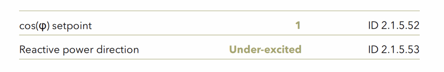
For the fixed cos(phi) :
o Set the desired cos(phi), typically 0.96.
o Use underexcited, either as an inductive load so that the effect is a voltage drop on an inductive line.
-
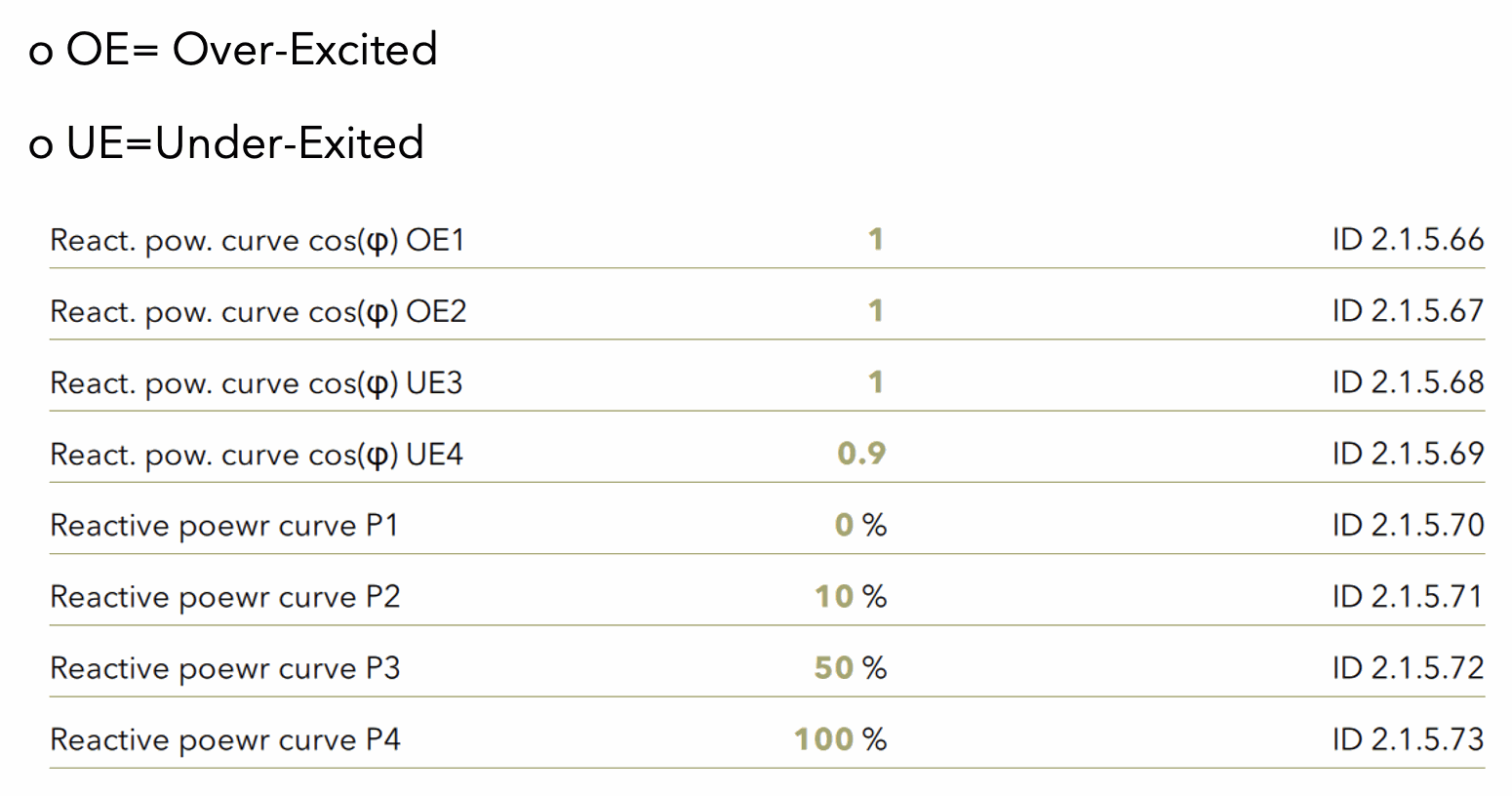
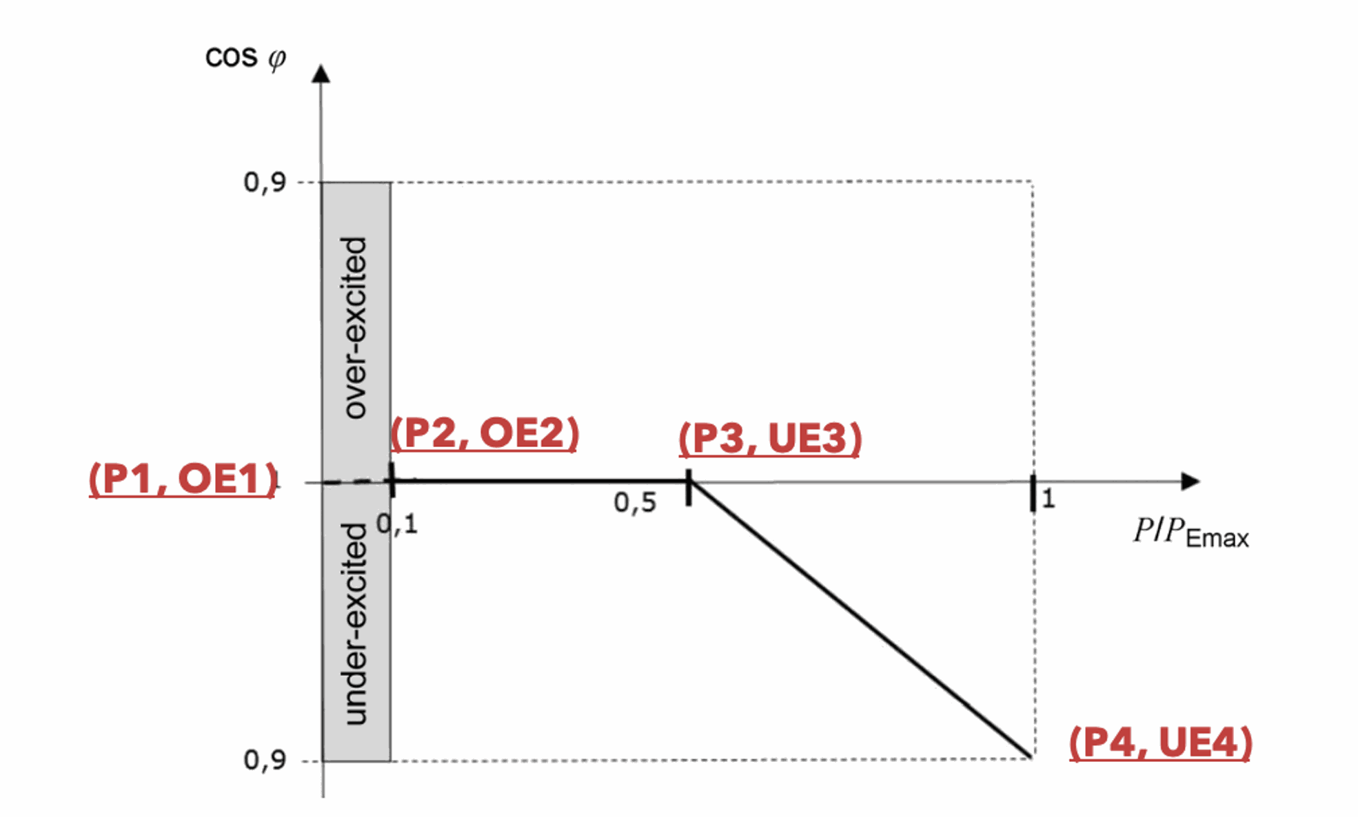
For cos(phi) as a function of power: It is possible to define the point at which the reactive power is produced. This is because when production is low, the voltage increases are small and do not require countermeasures. The signs of the generated reactive power are explained with the titles:
-
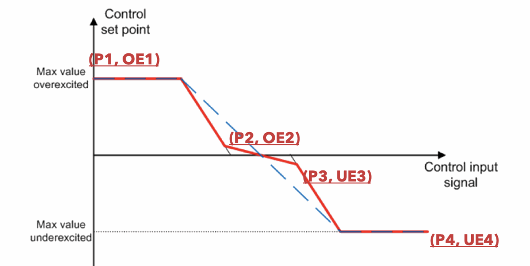
The general curve is shown below:
And their typical use is:
-
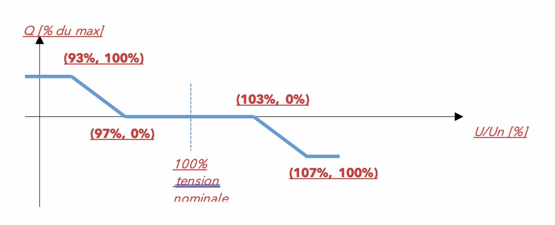
For the voltage-dependent cos(phi): In this case, reactive power is only generated when the voltage rises (or falls) depending on certain threshold values. The maximum reactive power (100%) corresponds to a minimum cos(phi) of 0.9.
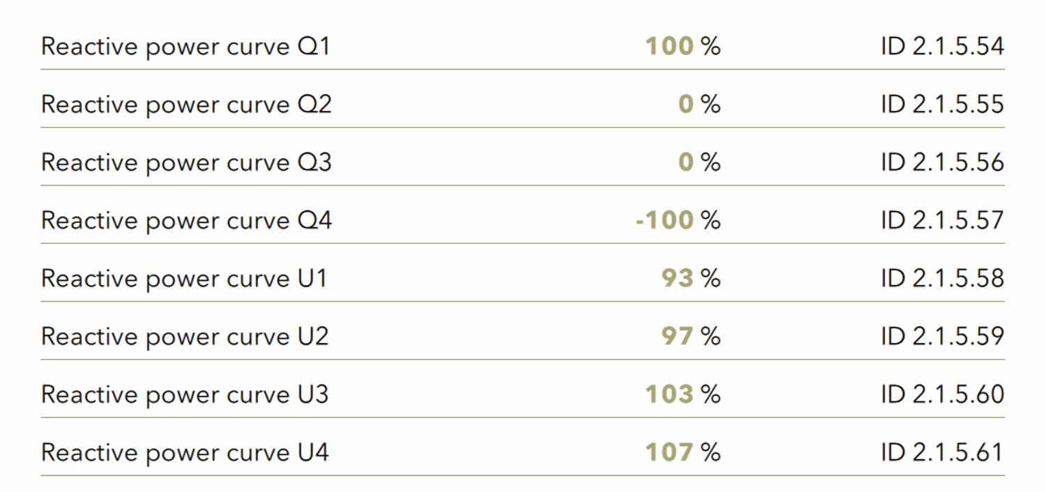
The control signal is the voltage and the controlled variable is the reactive power:
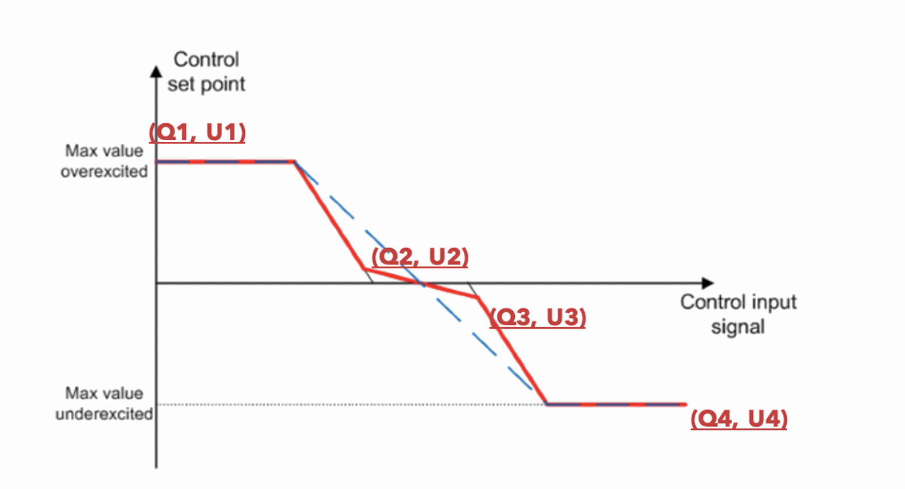
The typical use of this function is listed below:
-
For fixed reactive production: Use setting ID 2.1.5.51 in % of nominal. This is useful for a system where an external controller dynamically controls the reactive power by sending setpoints via Modbus. The reactive power remains limited by the cos(phi) min, which is 0.9 by default.
Note: In case of stability problems, the reaction speeds (PT1 filtering) can be adjusted with ID 2.1.5.62. Details can be found in the VDE and EN standards given as reference.