Basic concept
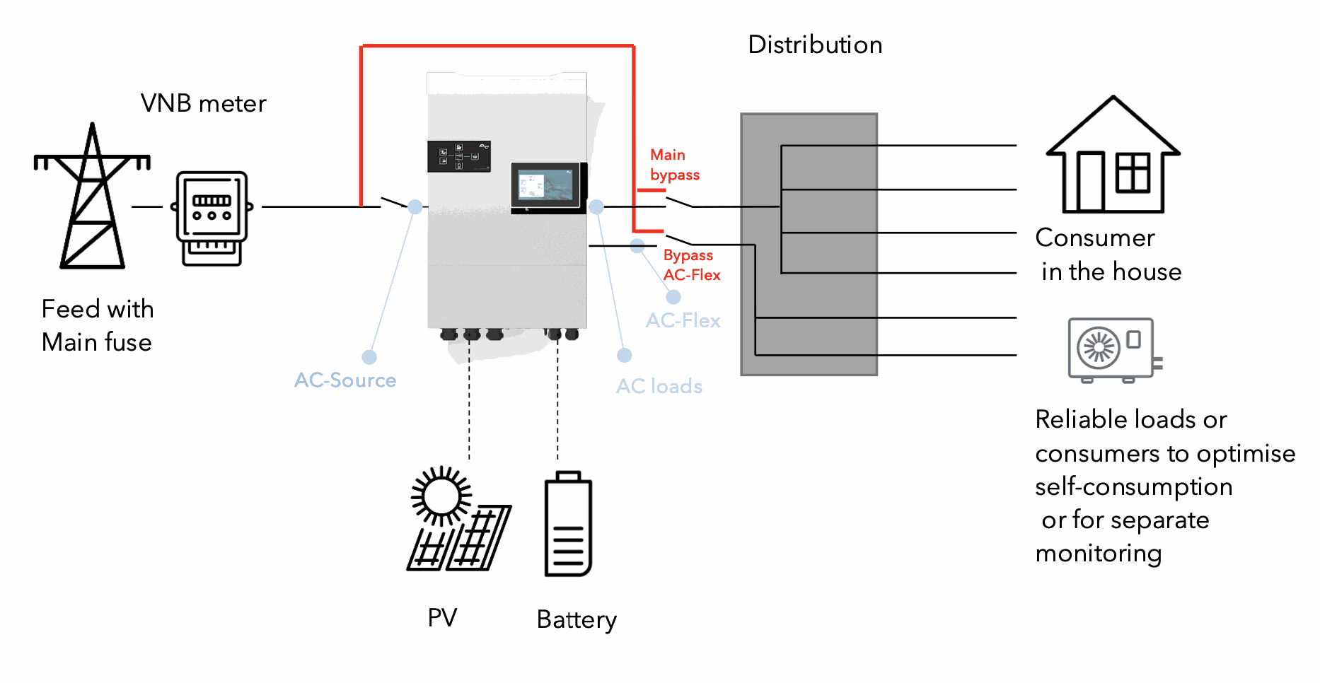
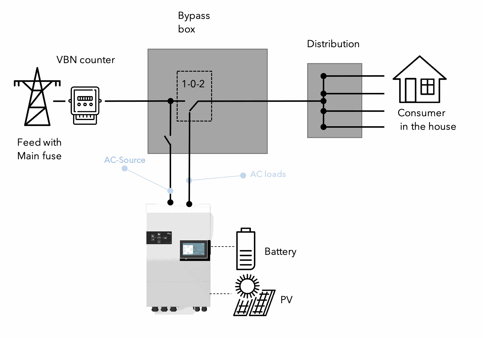
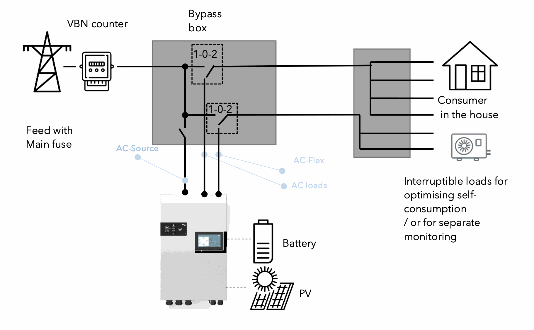
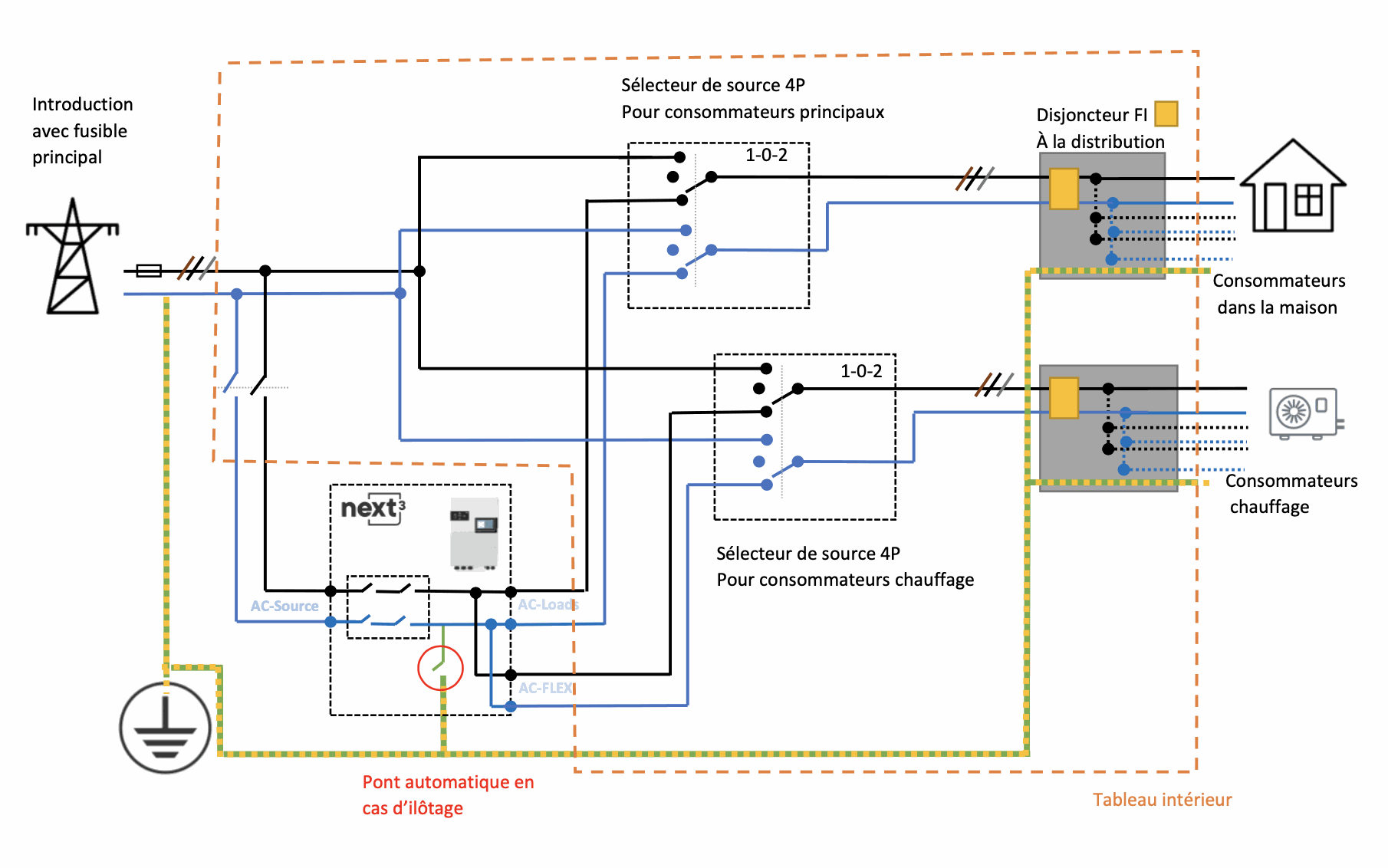
The next3 is an all-in-one hybrid solar inverter (with battery) with backup functionality. This device is connected between the grid and the house, directly after the introduction and the main meter. The grid is connected to the AC-source terminal, the loads to the AC-Loads and AC-Flex terminals. An internal relay in the unit next3 opens in case of mains failure and the terminals AC-Loads and AC-Flex can be supplied from the batteries in case of main failure. This internal relay complies with the norms for the grid (double relay with contact monitoring, 4 pole break). The detection follows the requirements of the grid (voltage, frequency, anti-islanding,...). When the grid is back, the next3 synchronizes to the voltage and closes is internal relay when the voltage is well in phase, avoiding any voltage jump.
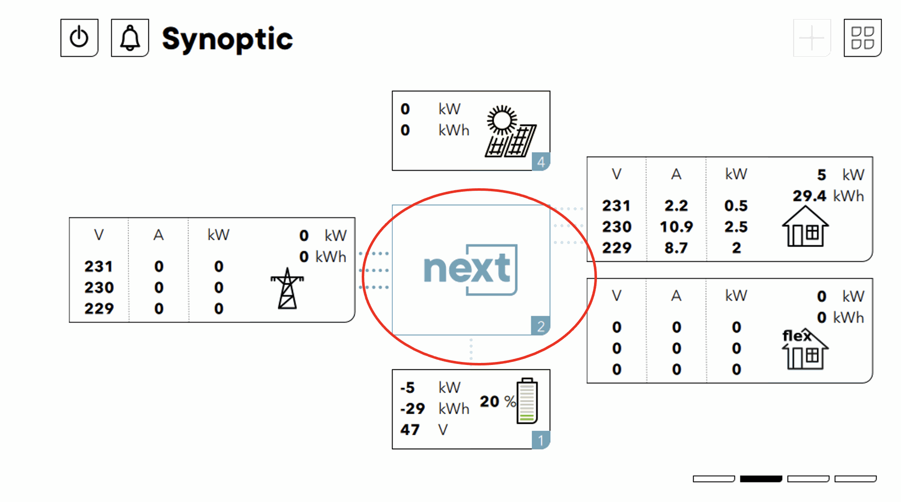
The AC Flex output is a second output of the inverter that can be controlled (internal relay in the unit) or simply used to measure consumption separately (next3 monitors/records all current flows).
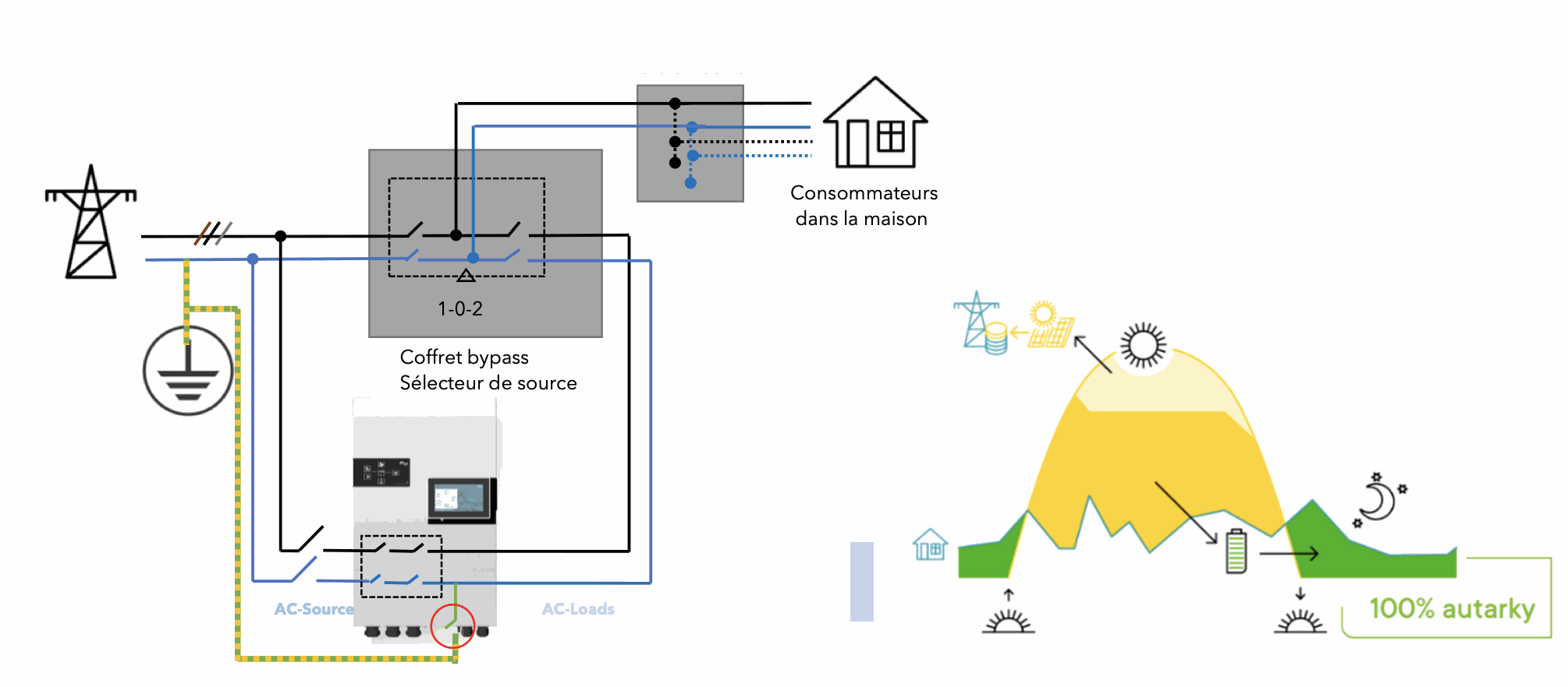
A bypass should be installed to provide redundancy in case of failure. A double bypass can be installed if AC-Flex is used.
Example of a next3 integration to an installation with existing electrical cabinet:
-
an added bypass box/table
-
of surge arresters and DC protection devices for solar installations
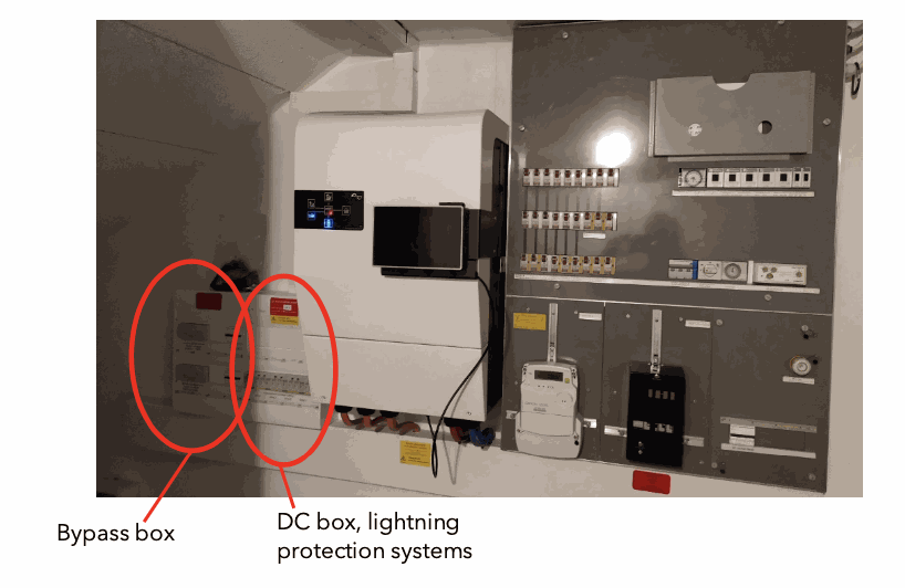
In the (Swiss) regulations, DC and AC must be separated. The DC wiring must have is own electrical panel. Precautions must also be taken so that the unit can be stopped easily and clearly in case of problems.
Technical principle diagram of the unit
schematic representation of the next3
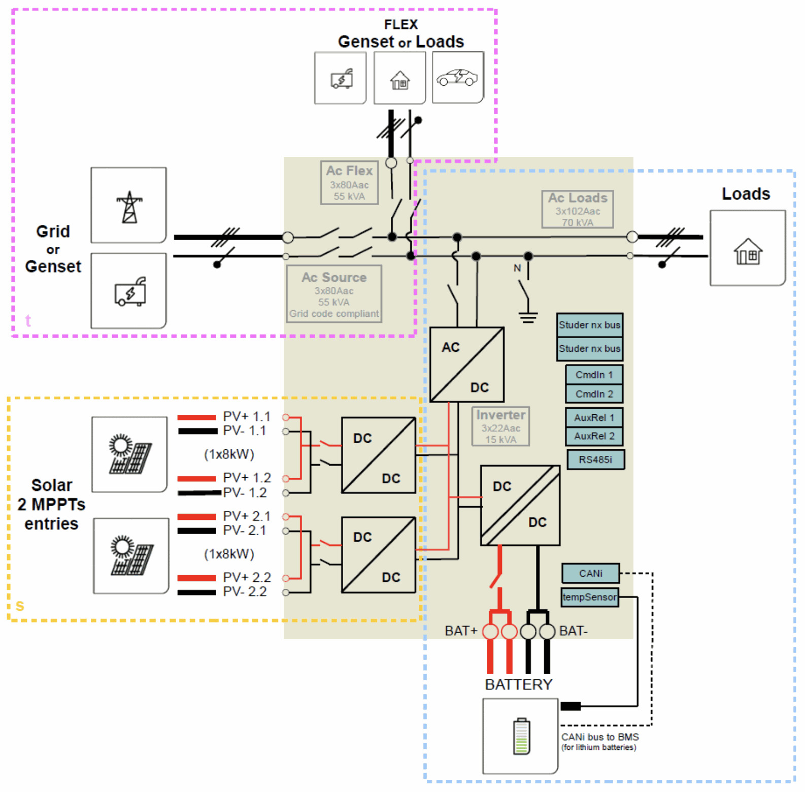
Note: The relay that disconnects the feeder complies with the grid directives. The functionalities concerning the grid interaction have been certified (anti-islanding , NA protection, frequency behavior, ...). The grid standard must be selected by the installer during commissioning according to the requirements of the DSO. For Switzerland, the network operators usually require the German standard VDE-ARN4105 corresponding to the requirements of the RR-IPE/ NR7 2020.
Electrical schematics AC
The next3 has connections and a transfer capacity (max. current flowing through the unit between AC source and AC loads) of 80Aac. This is usually more than the ampere rating of a standard house connection. So the next3 is protected by the input fuse. However, it is good to install a circuit breaker and bypass to isolate the unit in case of maintenance. Thus, the AC source input can be isolated by this circuit breaker and the AC load output can be isolated by the bypass.
The bypass comes in different types:
-
automatic or manual
-
single (for AC-Load) or double (for AC-Load and AC-flex)
Note that a bypass must always pass through a fully off position and implies a switching delay and thus a micro-interruption.
The neutral conductor can be left continuous (solid neutral) or interrupted, but this must be communicated to the unit during programming, as it must manage a correct neutral-earth connection. This connection neutral-earth must comply with the installation standards of the respective country. See below for comments and diagrams.
A simple, full automatic bypass box is available from Studer-Innotec or can be made by an electrician or installed in the main distribution box of the house if space is available.
Simple manual bypass
In this case, the source switch must have a zero position that guarantees a separated position.
Examples of components that can be used for this manual source selector switch :
-
HIM404 (Hager) 4P 40A
-
HIM406 (Hager) 4P 63A
- HIM408 (Hager) 4P 80A
-
OT40F4C (ABB) 4P 40A
-
… non-exhaustive list


Manual double bypass
The same type of manual double bypass can be realised with two switches if the AC-FLEX output is used. Indeed the output AC-flex and AC-Loads should not be connected together :
Automatic bypass
In this case, an automatic bypass is carried out by relays controlled by the presence or absence of voltage.
As in any Grid inverter, a mechanical interlock is mandatory to ensure that no short circuit is possible. An electrical interlock of the controls guarantees a defined state. The priority command to the next3 is given by a relay K3.
When the next3 provides a voltage, it is activated and switches off the network. Delays provided by K4 on the switching on of K2 (changeover to inverter) and K5 on the switching on of K1 (changeover to inverter) and K5 on the switching on of K1 (switch to grid) guarantees real interruptions which allow loads to be demagnetised and phase jumps to be avoided. This is for cases where the inverter was running but not synchronised to the grid. The 100ms delay is sufficient. Manual forcing on the grid is possible with a circuit breaker F2 that interrupts the coils of K2 and K3. coils of K2 and K3:


An automatic bypass box of 25A/40A/60A/80A can be ordered as an accessory directly from Studer-Innotec.

Automatic bypass with emergency stop (for firemen)
In this case another contactor allow to separate the input of the next3. The The contactor K3 becomes a forced contactor that separates the input. The K3 as well as the reverser K1-K2 can be switched off with an emergency stop. A contact is given on one of the inputs of the next3 to bring it to a complete stop. The opening of the fuse F2 allows to force the supply via the grid.


The settings of control input of the control in emergency stop is done in the menu system :


For use in emergency stop mode, the control input must be set up with an activation when the contact is lost. So we need a reverse logic. The setting of the control input is done in the device menu (swipe from the system menu):


The contact is done via the 12V cable provided with the input 1.
Automatic double bypass
This is the case when the AC-Flex terminal is used and should be bypassed automatically at the same time as AC-Loads.
A second inverter can be added, with a similar scheme and control logic to the first. The two bypasses must be independent. Particular attention must be given to the management of neutrals which must not be recoupled after separation for the IF protections to work properly.
The neutral conductor system
The earthing system must be connected in accordance with the relevant local standards and regulations (ITTO) depending on the circumstances in the building: TNS or previously TNC.
To ensure safety, the next3 with transfer is equipped with a programmable grounding relay capable of connecting the Neutral wire (load side) to earth (device housing).
The relay can be configured in the following mode :
- interrupted by passing through the device and an earth-neutral bridge is created in the device when the device is in island mode (automatic case by default self-managed). This case is for an interruption of the 4 poles L1, L2, L3, N. This earth relay is open in case of connection to ACsource, because in this case the neutral regime is fixed by the link made to the input. In case of islanding, the internal T-N relay switches, fixes the neutral potential and allows the downstream fault current protections to work properly.
 The standards for photovoltaic inverters require that all poles are interrupted in case of islanding detection and this is why Studer-Innotec recommends this configuration and this is the default configuration used by the next3. In this case the contactors/circuit breakers/bypass should be 4-pole (L1-L2-L3-N).
- continuous (solid-neutral=a physical bridge must be made between the input-output neutral terminals and these are never interrupted). In this case the circuit breakers must be for an interruption of the 3 poles L1, L2, L3. In this case, the internal earth relay is never switched (always open). The internal neutral relay is not specially switched ( !different from the Xtender). THIS CONFIGURATION IS NOT RECOMMENDED as it poses risks if it is not carried out correctly.

In all cases of operation the T-N link must be correct to allow the fault current protections to operate in the different modes of operation: grid connected and island.
The installation regulations (ITTO) must be complied with as a matter of priority and the safety of persons must be ensured.
safety of people.
An example is given for the double manual bypass with the following schematic diagram. Here the fault current protectors (FI) are placed after the bypasses since the neutral grounding point can change:
Various checks are carried out and give an error message when an earth fault is detected:
In offgrid self-managed mode:
- A check of the T-N insulation is done on the loads (AC-Load/AC-FLEX) before starting. If OK the internal T-N relay is closed and a continuity test is performed. If everything is OK the inverter can start in OFFGRID.
-
- If there is a problem during start-up: Check that there is no bridge between N and earth downstream of the inverter.
- If there is a problem during start-up: Check that there is no bridge between N and earth downstream of the inverter.
- When the presence of the network is validated (frequency, voltage, waiting time OK), the T-N relay is open, there is a discontinuity/isolation check. If OK the transfer relay is closed (relay noise is heard). Then a TN continuity test is performed and the transfer relay is reopened if the neutral is relay is re-opened if the neutral is isolated.
-
- In case of problems with the connection: Check that the bridge between N and earth ahead of the inverter is present (when entering the building).
- In case of problems with the connection: Check that the bridge between N and earth ahead of the inverter is present (when entering the building).
- When switching back to island, the transfer relay opens, there is a discontinuity test, then the TN relay closes and a continuity test is performed. If one of the tests does not pass, the inverter shuts down. There are 5 tests and then a final shutdown.
The isolation test checks for an impedance of at least 30kOhm.
In solid neutral mode:
- A neutral ground check is performed and an error message is given if this is not the case. This test is carried out at each transition: when the appliance is switched on (no operation), when switching from island to mains operation), when switching from island to mains connection (1 test just before closing the relays and one test just after) and when switching from grid connected to island. (not permanently because the solar system must be switched off).
- This control is done by measuring the ground-to-ground impedance.
- The unit shuts down completely. There are 5 restart attempts in offgrid before a final shutdown. As the inverter cannot connect, there is no switch to offgrid.
-
- In case of problems with the connection: The correction to be made is to make the missing T-N link at the building introduction and the solid-neutral bridge correctly.
- In case of problems with the connection: The correction to be made is to make the missing T-N link at the building introduction and the solid-neutral bridge correctly.
- At each test there is a ground error message (message ID ....) and at the final stop a message ID xxx
The default operation of the unit is for a neutral control managed by the unit. If a change is desired, this is done in the system menus :

And on the configuration icon:

Select "self-managed" or "solid neutral" for the earthing management.

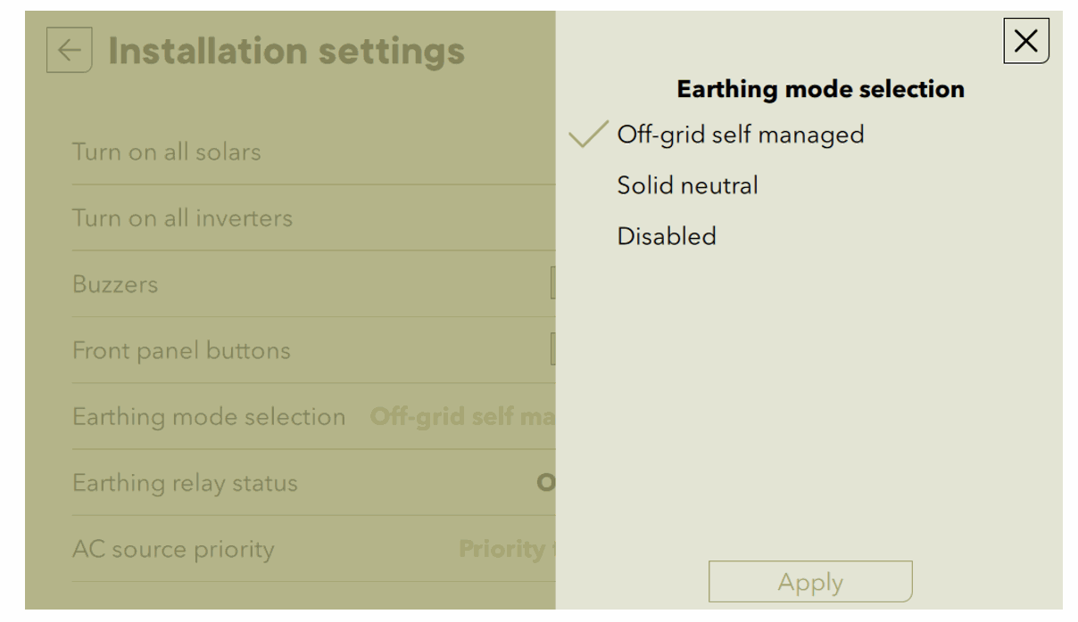
This mode should only be changed after the necessary precautions have been taken to ensure that the the neutral system is correct and ensures the safety of people.
The next3 is a three-phase voltage source with neutral. The neutral must be distributed in the house at the same time as the phases, otherwise the connected loads will be destroyed. If the neutral is not connected (floating), 230V consumers can have up to 400V depending on the balance of the loads connected to each phase.
Particular attention should be paid to this point when installing in old houses with a TNC regime and not TNS as required by the current standards.
In operation, the AC residual current (sum of all phases and neutral) is not controlled by the next3. This functionality is provided by the fault current circuit breakers (FI) which are placed by the installer downstream.
Isolation tests
When commissioning an electrical system, insulation tests are carried out on the wiring (in some countries according to local regulations). They are carried out by applying high voltages to the cables and measuring the leakage current. This procedure must be carried out without the next3 in the loop. The overvoltage protection included in the next3 invalidates the tests, as the next unit is protected against mains overvoltages by electronic voltage limiting elements (VDR).
The insulation between the circuits and earth is tested in the factory for each next3 device manufactured in accordance with the IEC/EN 62109 and IEC/EN 62477 safety standards before final assembly of the surge protection devices. The manufacturer Studer-Innotec therefore guarantees the good insulation of the device to earth in this case. The installer must check everything concerning the wiring without the presence of the next3.
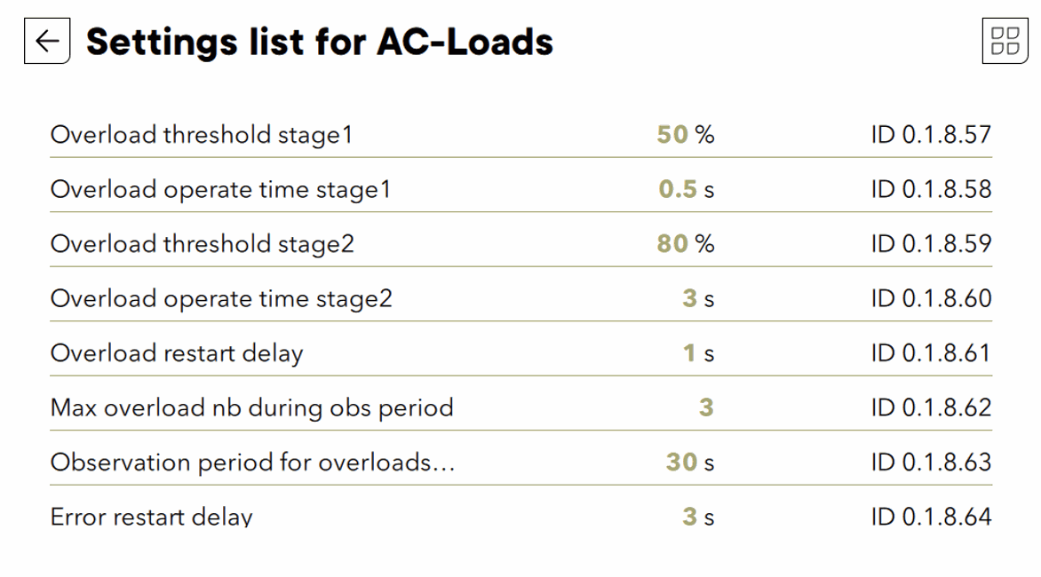
Short circuits current and overload behavior
Bo
In stand-alone operation (offgrid), when the inverter is not connected to the grid but is operated with batteries, the next3 cannot pass the standard tests for short-circuit currents that are carried out when commissioning an electrical system due to its output impedance.
Nevertheless, in the event of a fault (short circuit, overload), the current is electronically limited by the unit. If a short circuit occurs, it is detected and the unit switches off automatically. Safety is guaranteed in this case. In the island situation, the electronic current limitation is 45A in the event of a short circuit phase-neutral in the cold state and 65A in the event of a short circuit phase-phase.
A next3 detects a short circuit when the voltage drops to less than 50 % of the nominal voltage with maximum current limitation, then the unit switches off after 0.5 seconds. In case of a limited overload, if the voltage drops to less than 80 % of the nominal voltage with current limitation, the unit switches off after 3 seconds. By default, the unit will attempt to restart up to 3 times after 1 second. The number of attempts is reset to zero after 30 seconds of normal operation.
All these parameters can be set in "Expert" mode. Studer-Innotec recommends leaving them at the default values.
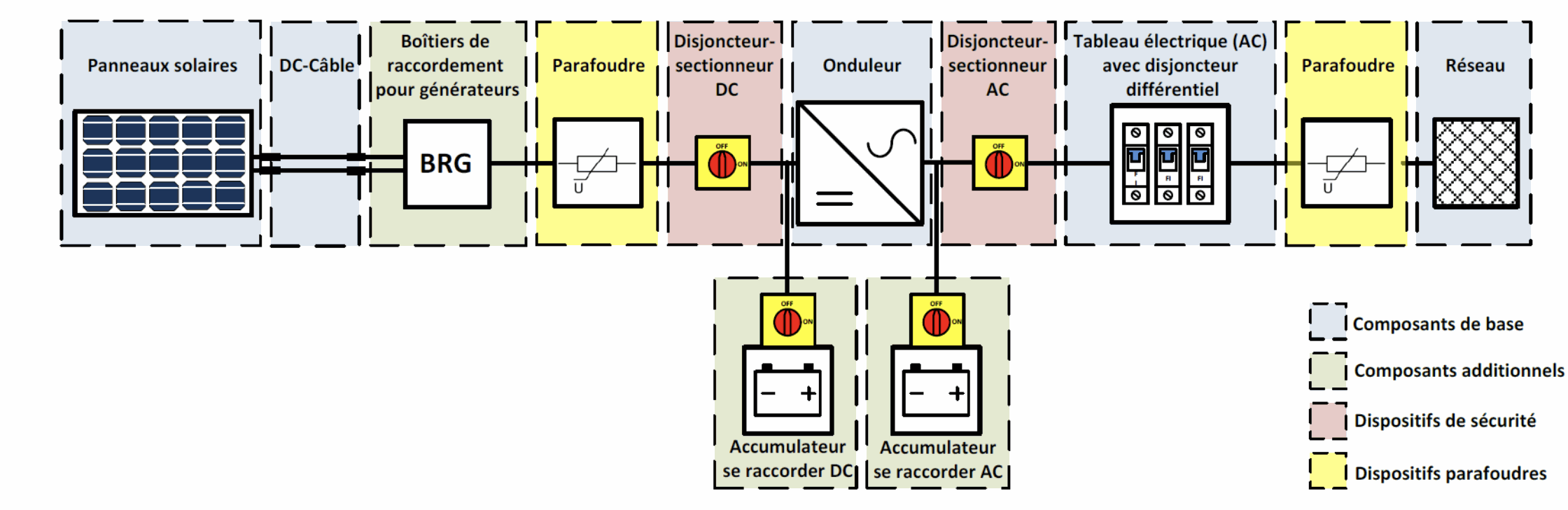
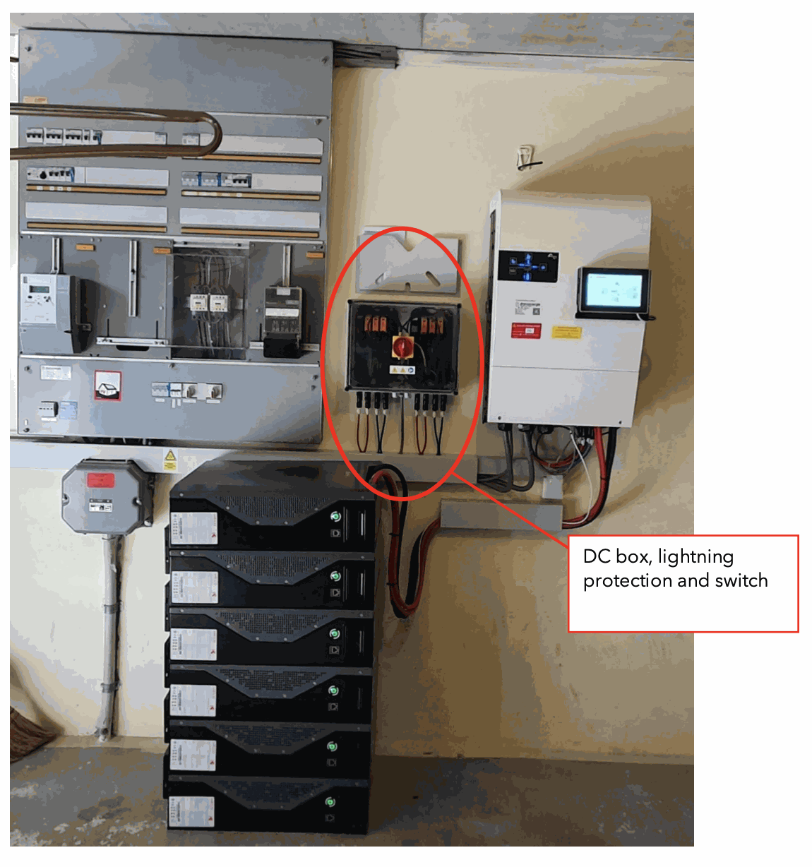
Schematic DC, PV dimensioning
The installation must be done according to the local standards. In Switzerland, it is now required that AC and DC are separated. The DC wiring therefore has its own table and its own channels.
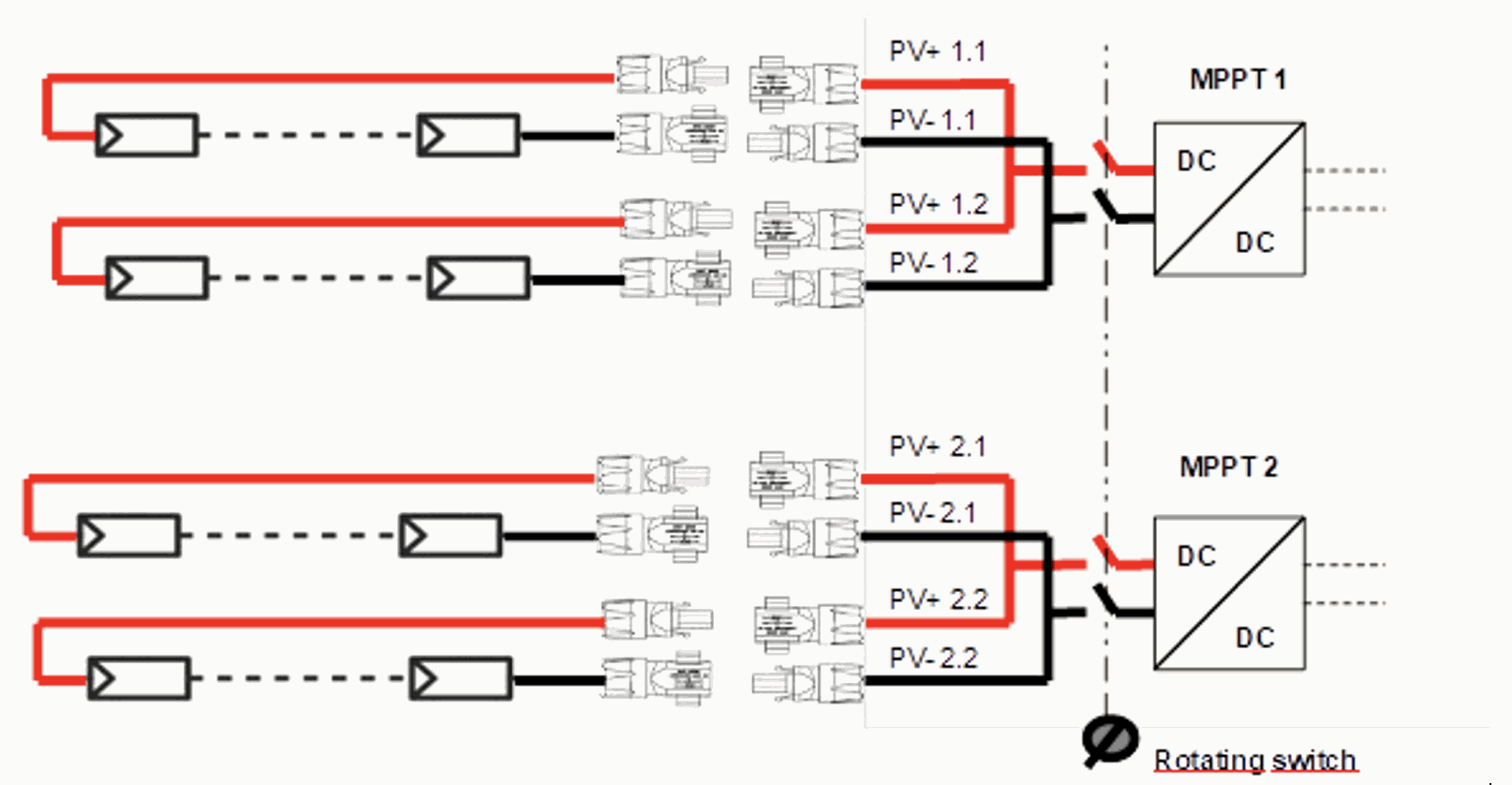
The next3 has two independent 8kW PV inputs that can be used to operate two strings of modules in series. Each MPPT can convert up to 22Adc of photovoltaic (PV) current during operation. For this reason, each MPPT has 2 inputs and up to 4 strings can be connected to the unit. The two upper inputs (MPPT1) are internally connected, as are the two lower inputs (MPPT2). The parallel connection of two PV strings for one MPPT can also be done outside the next3, e.g. with a Y on the roof. The short-circuit current of the panel max. is 27A.
The DC voltage of a string must be less than 900V. For starting, the voltage must be greater than 350V.
There is a switch on the unit with which the solar modules can be switched off.
PV protective housing
Externally, the only protection to be added is surge arresters depending on the keraunic levels but without obligation.
In addition, precautions must be taken to ensure that the device can be easily and clearly stopped in case of problems. Additional external switches are not mandatory but are recommended for clarity.
The DC isolator of the solar modules is installed directly on the next3 :
Professional solar installers are familiar with the requirements and there are no DC boxes supplied by Studer-Innotec.
 Professional solar installers are aware of the requirements and there are no DC boxes provided by Studer-Innotec.
Battery protection
A fuse should protect the battery cables.
With a lithium battery, the protection devices are internal to the battery, which also protects itself with a contact in the event of simple overcurrent or incorrect use of the battery (undervoltage, overvoltage). An additional fuse is usually not required. Please observe the battery manufacturer's instructions.
For lead-acid batteries, a fuse is required at the positive terminal closest to the battery.