What's modbus?
Modbus is a general communication term that includes a lot of things. There are two physical layers to transmit MODBUS: RTU (=RS485) and TCP (on local ethernet network). Each device has its own way to speak MODBUS: it is the specific list of registers. To communicate in MODBUS with one device, the list must be adapted and it requires development. It is not plug and play because it is not standardized. A device can have two positions in a MODBUS communication: it can be master (initiates requests) or it can be slave (only answers to requests).
This technical specification describes the "Studer Next Modbus Protocol". This protocol enables the control of a Studer Next system from a third party device (PLC, SCADA, etc.). Using this protocol, it is possible to read and write properties.
Conventions used
Numbers starting with a "0x" prefix are hexadecimal numbers. Otherwise they are decimal numbers.
List of acronyms
PDU Protocol Data Unit
RTU Remote Terminal Unit
MBAB Modbus Application
TCP Transmission Control Protocol
IP Internet Protocol
CRC Cyclic Redundancy Check
Modbus implementation
The next gateway device offers a way for installers/integrators/developers to access and control a Studer next system using the Modbus RTU protocol. The Modbus protocol is standard and well known and used in the industry field. For more information regarding Modbus, please see the Modbus official web page:
www.modbus.org.
Protocol overview
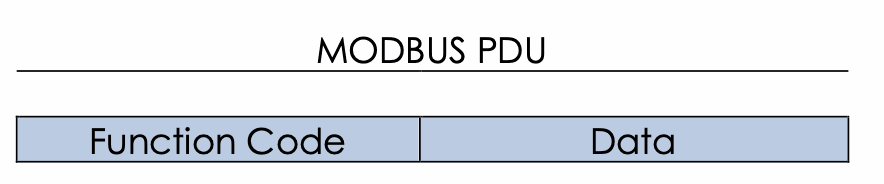
The Modbus application protocol defines the Modbus Protocol Data Unit (PDU) which is independent of the communication layer. This PDU has the following format:
RTU
On RS-485, the standard Modbus PDU is encapsulated, and fields are added in order to make communication possible over a serial line.

The Slave Address field (8 bits) is used by the Modbus Master to access a slave device on the bus as explained in section 3.1. The CRC field (16 bits – CRC16 Modbus as described into the 6.2.2 chapter of Modbus_over_serial_line_v1_02.pdf document) with the low byte first and high byte second is used to check if the frame transmission is done successfully.
TCP
By using Ethernet or Wifi as physical layer, a TCP/IP connection is available. A new 7-bytes header called MBAP (Modbus Application Header) is added to the standard Modbus PDU.
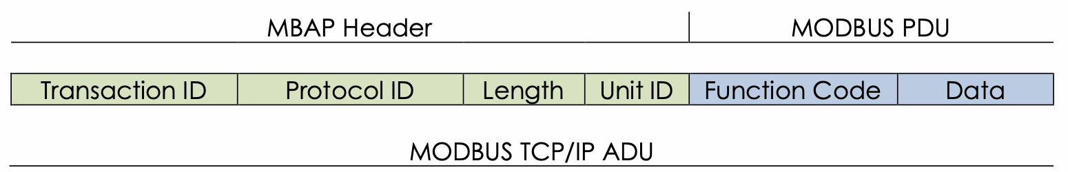
The Transaction Identifier (2-bytes) is set by the client to uniquely identify each request. The Protocol Identifier (2-bytes) is also set by the client and always equal to 0x0000. The Length field allows to know the number of bytes contained in the PDU message. Finally, the Unit identifier is equivalent to the slave address used by Modbus RTU. This field is the identifier of the remote slave as explained in section 3.1.
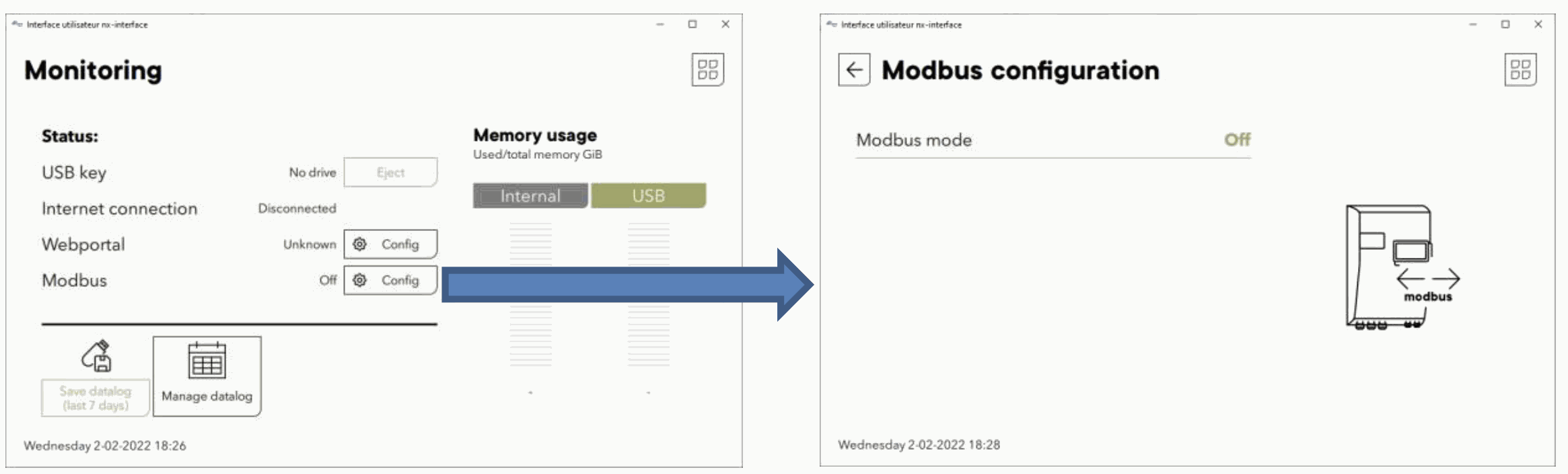
Configuration
Next gateway has several Modbus configurations according to the server mode. The Modbus configuration page is available under “Monitoring”. By default, both RTU and TCP servers are disabled:
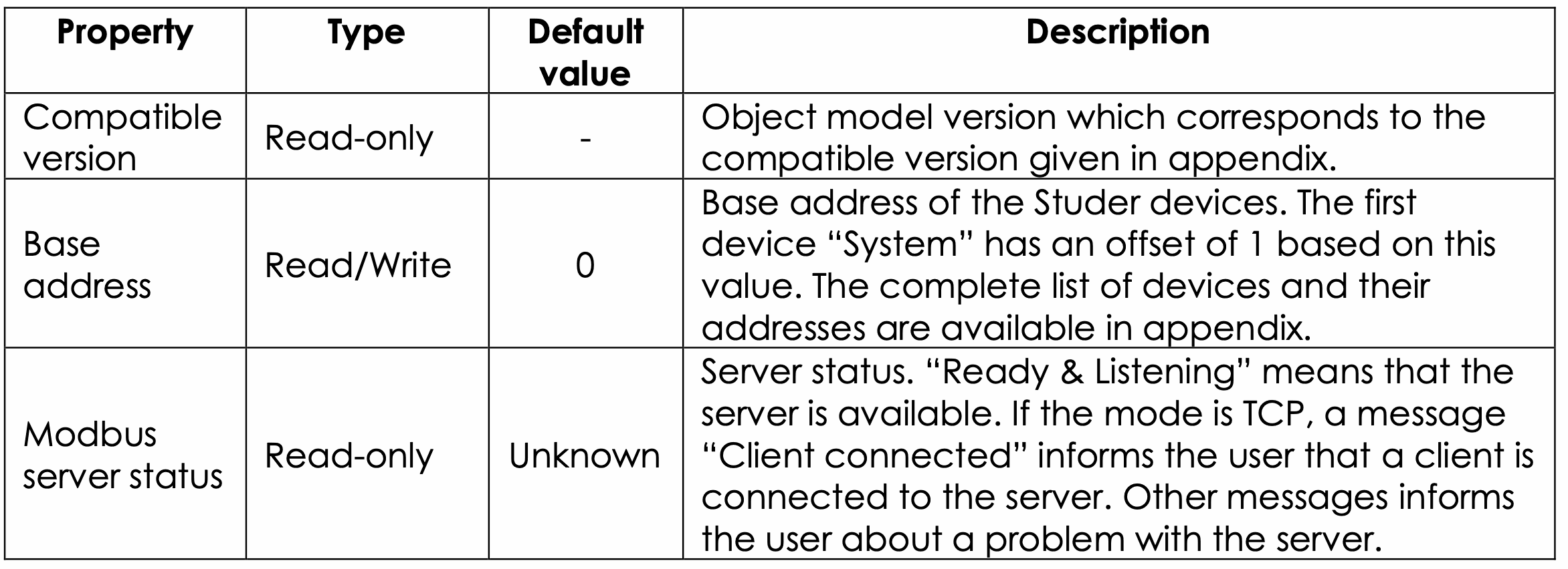
When selecting a mode, several properties will be displayed in this view. Some properties are common to both servers:
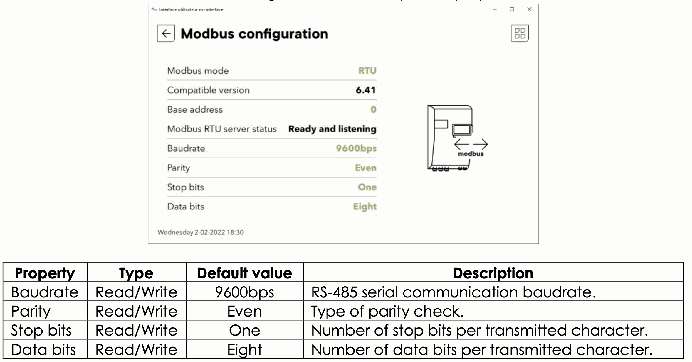
Hereafter is the view of the RTU configuration and the specific properties list:
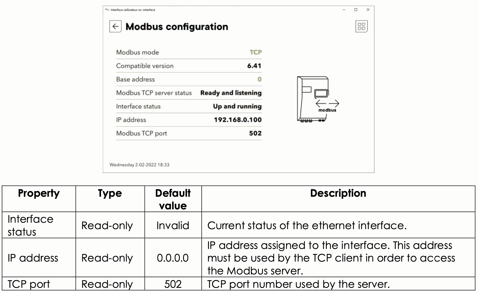
Hereafter is the view of the TCP configuration and the specific properties list:
Frames endianness are defined by the Modbus standard and are big endian, so MSB (Most Significant Byte) is sent first on the medium. For example, a 16 bits value of 0x1234 will be send 0x12 then 0x34 on the medium.
Hardware connection
The bottom side of the nx interface gateway gives the access to several connections shown below:
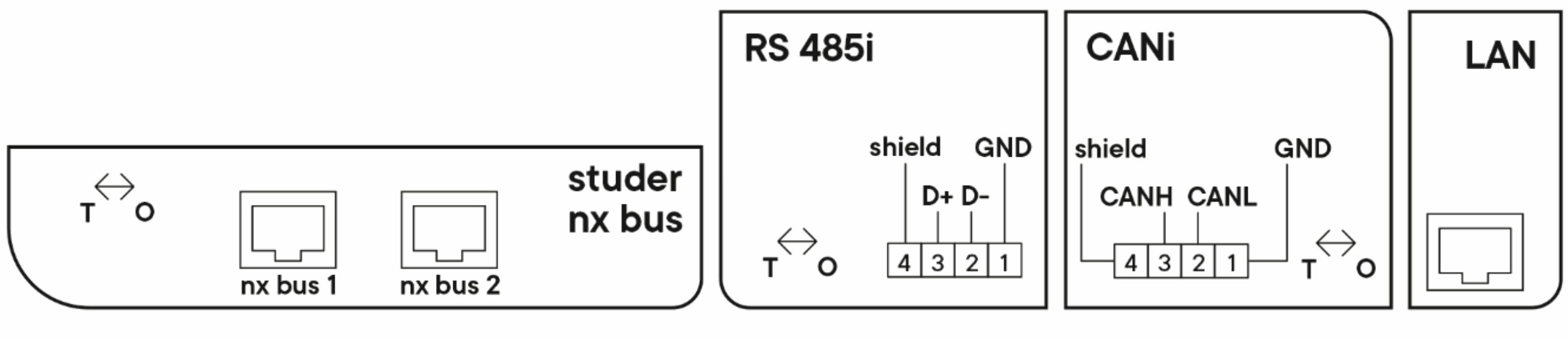 Modbus RTU:
Electrical interface: RS-485i Connector type: Phoenix MC 1,5/ 4-G-3,5
Modbus TCP:
Electrical interface: LAN/ Ethernet Connector type: RJ-45
Modbus for next system
The Modbus for next system is based on the next “Object Model” datamodel, that is described in the appendix. Note that accessing a next installation using Modbus is dependent on the version of this Object Model. This version can be found on the first page in the appendix.
After a major update of the next system, with a different Object Model version major number (the left number, e.g. going from 6.41 to 7.0), the devices addresses can change, and the properties register addresses can change as well.
Therefore, always make sur that the version in this documentation appendix has the same major version as the version shown by your next gateway device.
Also, as a good practice, always start your Modbus controller program by reading the Object Model version property of your gateway device, and check that the major version number (left number, most significant 16bits of the property) matches the one you used during implementation.
Addressing Studer devices
The “Slave Address” field for Modbus RTU, or “Unit ID” field for Modbus TCP is used to identify the “Object Group” instance that needs to be accessed.
“Object Group” concept is used to describe part of the system in a generic way (same concept as Object Oriented Programming). A list of all Object Groups and their content can be found in the appendix. Note that the first Object Group is at offset 1, to prevent using the slave address 0, which is reserved for broadcast use in Modbus protocol. Broadcast is not supported by next devices.
For example, the “System” Object Group is at address offset 1, therefore if you set the “Base address” property to 0, you can access the “System” group at device address 1.
Unicast adresses
Unicast accesses enable the possibility to access a single object group instance in the installation.
Mutlicast adresses
Not currently planned
Response delay
The response delay of the gateway is usually a few milliseconds. However, it depends on the internal Studer bus load (number of devices, datalog transfer time, etc …).
In extreme cases, this delay can be up to 1 second. This value must be taken into account when choosing a timeout duration in the master implementation.
It is strongly recommended not to flood the gateway with multiple requests. The correct way to communicate with the gateway is to send a request and to wait for the response before sending the next request. It is also how Modbus is intended to work.
If no response comes from gateway after a timeout delay, we can consider that the timeout is over, and another request can be sent. This timeout delay value must be bigger than the timeout value of the gateway (1s.). For example, a good timeout value in the master implementation could be 2s.
For both read and write operations, a rate limitation mechanism has been implemented to avoid flooding the device with requests. The limitation has been fixed to 20 [req/s] and must be followed by the master.
If the time between two requests is not followed, a delay has been added before sending the response to the master
Studer next mode function code
Studer Innotec next properties are accessible using Modbus Function code. The following table maps the next system function to the Modbus Function code.

Modbus uses the same mechanism between the function code to access registers. The request sent by the master always contains the Function Code, the Register Starting Address and the Quantity of Registers to be access. Some more information can be mandatory inside the request depending on the Function Code. Please see Modbus specifications for more information.
Modbus Request general structure :

Modbus registers are defined as 16 bits registers. These registers are accessible using a 16 bits register address. For the Studer Innotec implementation, values are mostly encoded in 32 bits float format. So it will be needed to read/write 2 consecutive 16 bits registers to perform the full transaction (read/write parameter or read user info). Modbus register address have been defined for every parameter and user info.
Please see the “Technical specification – Next Modbus appendix" to get the full list of Modbus register.
Read object properties: read multiple holding registers
All properties accessible from a next gateway (e.g., nx interface) can also be accessed with the Modbus protocol. The corresponding Modbus function code to read properties is Modbus Read Multiple Holding Registers. The “Quantity of Registers” need to be set to the size of property, otherwise the gateway will send back an exception.
Write object properties: write multiple holding registers
All properties accessible from the gateway can also be accessed with the Modbus protocol. The corresponding Modbus function code to write properties is Modbus Write Multiple Registers. The “Quantity of Registers” need to be set to size of property, otherwise the gateway will send back an exception.
Write access limitations
By default, the write operation is performed on the volatile memory (RAM). After a restart of the installation, the properties are reset to the values contained in persistent memory.
To avoid reducing the persistent memory lifetime, the possibility to write properties in the persistent memory is limited. If the user wants to write persistently a property, he must firstly write a specific property related to modbus:
- Group: NextGateway
- Object: Modbus server
- Property: "write persistently with Modbus"
For the correct device and property addresses, please refer to the appendix. In order to prevent a user forgetting to quit the “write persistent” mode, a timeout of 60s will force to quit the “write persistent” mode and come back to default mode with volatile memory write operations.
Since the “Write persistent” mode is designed to be used only at very low frequency for parameters saving operations, there is an additional security implemented. If the user performs too many write accesses (currently set to 20 per minutes) in “write persistent” mode, the gateway will send back an exception and won’t execute the Write access.
Example code and available library
Studer Innotec provides a free Python library that enables access to next devices through Modbus (RTU & TCP). This library also contains example code for easier integration. These resources are available at this address:
https://github.com/studer-innotec/next-modbus