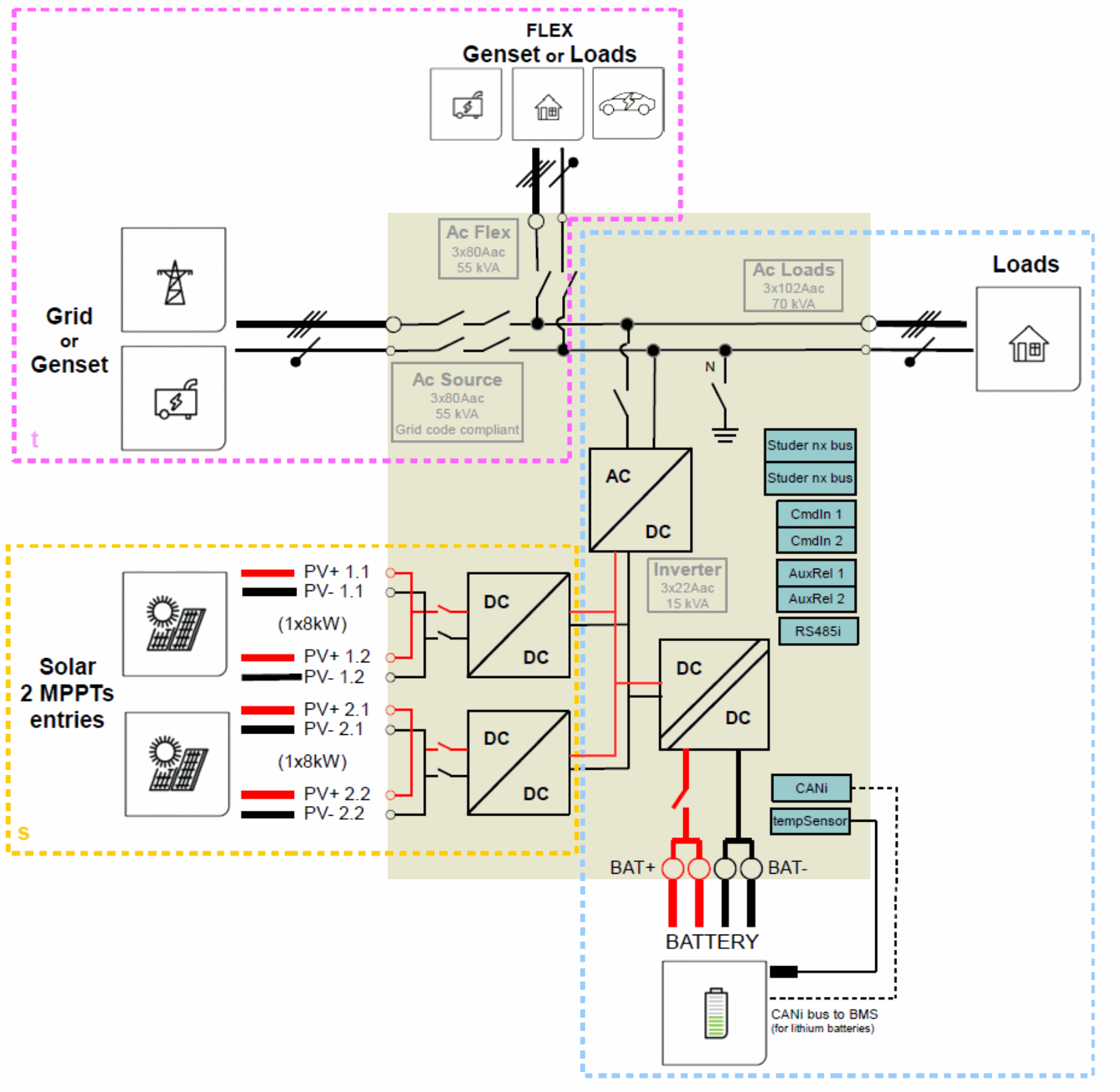
System block diagram
The general schematic diagram of the next3 st is given below. Letter s is for the solar and t for the transfer.
Dimensioning the battery
The battery bank is dimensioned depending on the user's daily energy consumption and the number of days of autonomy required. It is sized also in function of the wanted daily Depth Of Discharge (DOD).
The dimensioning of the battery must also consider the power and the type of loads that are connected to the inverter. As rule of thumb, the maximum power of a lead acid battery is given with the capacity divided by five (C/5), in that case if all the power of the next3 is wanted (16kW), the capacity of the battery should be at least16000*5/48=1666 Ah.
For lithium, see the maximum power defined by the manufacturer as lithium batteries are generally rated with a much higher current (C/3 or even 1C).
Take into account the surge power of loads, for example for motor starting and the overload capacity of the inverter to dimension your battery system.
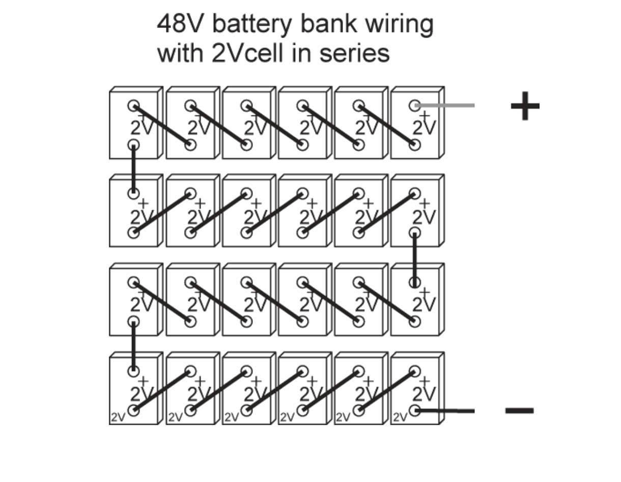
Battery bank design
Lead batteries are usually available in 2Vdc, 6Vdc or 12Vdc blocks. To get the correct operating voltage for the next3 (exclusively 48Vdc), several batteries must be connected in series. The capacity of the batteries can be increased using a parallel connection of several battery strings.
The various cabling options for the battery are presented in figures below.
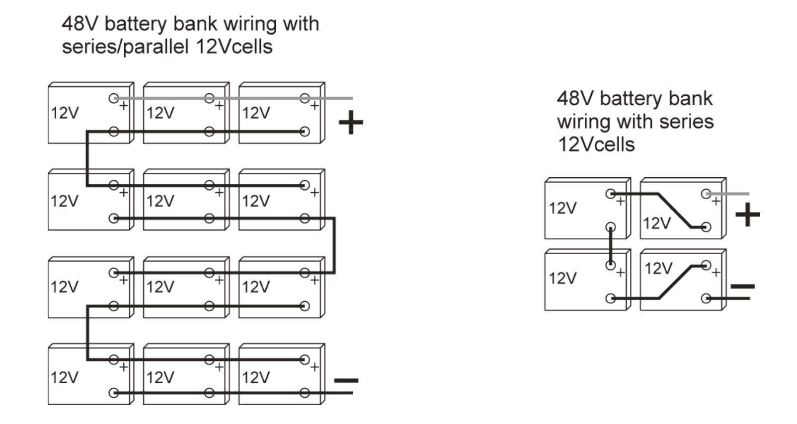
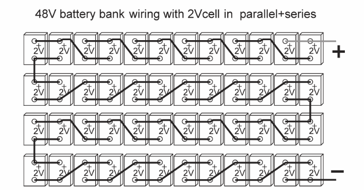
Strictly conform to the manufacturer's instructions for parallel connections, especially with lithium batteries.
Check the battery connections section for more information.
Sizing of AC protective devices
The source must be connected to the input terminals marked "AC-Source" with sufficient wire cross- section, depending on the power output of the source, and protected by a protection device of the appropriate rating. In any case it must be maximum 80A per nx3.
For people safety, we recommend using residual current devices (RCD) for loads at the output of the nx3. Take care of the earthing and neutral system for proper operation of the RCD. In any case, AC distribution must comply to the local standards and regulations, and generally, be realised through a distribution panel in an enclosure.
For cables protection, no downstream protective device is formally required if cross-sections of cable used for distribution satisfy to regulatory requirements for the largest rated output current listed on the nameplate of the next3. The next3 is protected against overload and short-circuit and will stop in those cases. When connected to a source, the upstream protection must stop short-circuits currents from the grid/genset.
When next3 connects to any AC source or AC Loads, there is never inrush current.
 Due to the source assistance function (Smart-Boost), the current at the output of the device may be higher than the rated current of the inverter. It is the sum of the current supplied by the additional source and the current supplied by the inverter. In this case, the dimensioning of the output cables will be carried out by adding the current indicated on the protection device located on the upstream of the unit, to the nominal current of the inverter.
If circuit brakers (CB) are installed at the output, we recommend B curve devices. They will be sized at maximum to the highest value
listed on the unit’s nameplate or by the addition of the first value plus the value of the input protective device. (i.e. inverter current + input current). As example, if the AC Source current is 50Aac per phase and knowing that the current of the inverter is (16000/230/3)=23Aac per phase, the total current on the output would be 73Aac per phase.
In any case it must be chosen according to the cable size downstream.
If the source assistance function (Smart-Boost) is not used; the size of the protection device for the AC-loads output will be established at a maximum value equal to the rated current of the inverter, or at the maximum value of the protection device at the input if that one exceeds the rated current of the inverter.
If the AC-source is not used the protective device will be sized equal or smaller than the smaller value indicated on the nameplate.
The next3 is intended to be supplied by alternative voltage sources such as the grid or a generator. Check that the rated voltage of the source corresponds to the rated voltage of the next3 model specified on the nameplate on the side of the next3.
The conditional short-circuit (Icc) is 45Arms at the output (AC-Loads and AC-Flex if configured as secondary loads) of the next3 when next3 is in stand-alone mode. DDR is mandatory for circuit breaker at output (AC-Loads and AC-Flex if configured as secondary loads) of next3.
The maximum prospective short-circuit current Icp of the sources connected to next3 inputs (AC- Source and AC-Flex if configured as secondary source) is 15kArms.
The minimum prospective short-circuit current Icp of the sources connected to next3 inputs (AC- Source and AC-Flex if configured as secondary source) is 1,6kArms.
The rated short time withstand current Icw of the next3 inputs (AC-Source and AC-Flex if configured as secondary source) is 16kArms during 500ms.
The rated peak withstand current Ipk of the next3 inputs (AC-Source and AC-Flex if configured as secondary source) is 25kArms.
PV string dimensioning
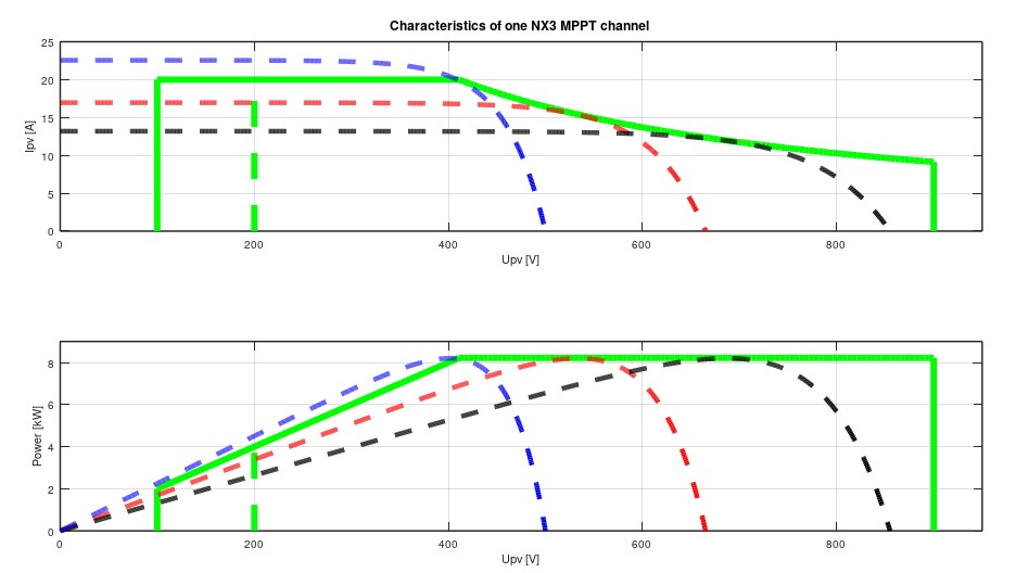
The next3 accept input voltages between 200Vdc and 900Vdc max. It starts operating from 200Vdc (start-up in the morning) and will continue to operate even if the voltage decreases down to 100Vdc (shut down in the evening, partial shading, etc.). The 200Vdc are necessary to detect a proper ground insulation of the PV before starting the system.
The nominal power of each MPPT channel is 8kW. The maximum current will be limited to 22Adc and the maximum voltage allowed is 900Vdc. See below the PV input characteristics.
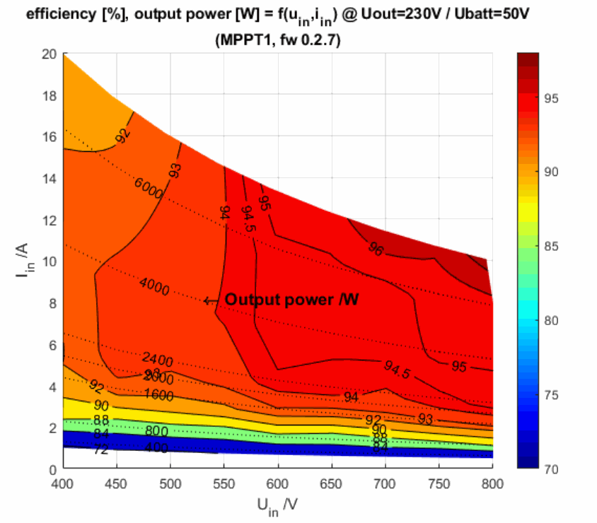
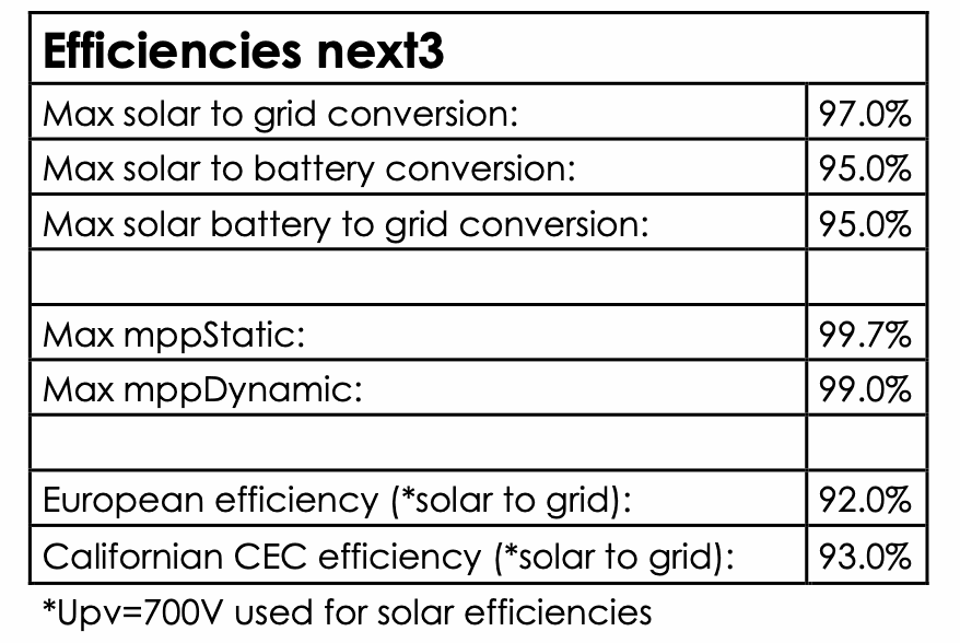
Tests of the efficiency performed by an independent lab showed the following result for the conversion efficiency from solar to grid.
Maximum current of the solar generator
The maximum short circuit current allowed is 27Adc. In operation the maximum current will be limited to 20A and the power per mppt to 8kW. Over dimensioning of the PV array is allowed but you have to ensure that the cable sizing and protections are installed according to the maximum short-circuit current.
In any case, the next3 will limit the PV current and/or the charging current (battery) to the rated and/or programmed currents. All those limitations are automatically managed by the next3 and there is no risk in case of over dimensioning the PV input power/current. The power production is electronically controlled and optimally dispatched in the system due to the PFD technology (Power Flow Dispatcher).
In some situation, the PV production could be limited by various other reasons at a systemic level because the next3 is in interaction with other elements. The battery has a charging current limit which can be further limited depending on the charging phase or the battery voltage. In offgrid application when the battery is full, the production will equal the AC loads. The maximal PV injection to the grid when there is no battery charging is 15kW (3x5kW grid feeding limitation).
Solar strings design
The solar generator is normally dimensioned to cover an important part or the entire energy requirement of the system. Once the PV power has been decided upon, it will be distributed among one or more MPPT units, wisely combining the modules among them. Modules with the same orientation and the same shading (if there is some) must be connected in the same string or there will be a risk of important mismatching losses.
These combinations in series and in parallel must be carried out according to the voltage and current limits of the next3 MPPT inputs. A margin to the Voc must be taken in countries with cold climate due to the thermal coefficients of the modules. Typically, a factor of 1.15 is taken in Switzerland up to 800m altitude (900V/1.15=782V), a margin of 1.2 between 800 and 1500m (900V/1.2=750V) and 1.25 above (900V/1.25=720V).
An example is provided below for a single MPPT string (example with 310W modules, 60 cells, 41Voc).
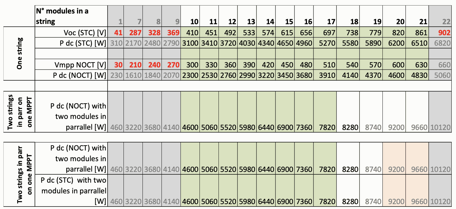
In the case of a 310W module with 60cells between 10 and 20 modules are recommended. 9 modules could be theoretically sufficient to start the inverter but in real conditions this could provide too little voltage.
21 modules in series are possible in hot countries but should be avoided in cold countries due to the increasing voltage at low temperatures (18 modules in cord countries). The open circuit voltage must be carefully checked with temperature coefficients given by the PV modules manufacturer.
When two strings are in parallel on one MPP channel, there can be up to maximum 17 modules in series order to avoid PV production capping. Up to 21 modules can be used with a high probability of capping.
In total between 10 (3.1kWp) and 84 modules (26kWp 4x 21modules) can be connected, giving a high flexibility for dimensioning the energy system.
Example for a 18kWp integrated rooftop
For a house surface of 8m by 12m, it is possible to place up to 7 modules in the length of the roof and 4 in the width. The principle of dimensioning was to take the maximum possible surface for this type of integrated module.
The chains are made, one with the two top rows, and the second with the two bottom rows. The two are in parallel for each roof slope. There are therefore 14 modules in a string for a power of 14x330 Wp=4.62kWp.
- Per roof panel for a MPPT : 9.24 kWp
- And in total with the two sides: 18.48kWp
The maximum and minimum voltages are respected with 14x41V=574V of open circuit in standard condition. This is well in the middle of the allowed range and guarantees both that the maximum voltage will never be reached (900V) and that the minimum starting voltage is assured (200V). Note: if the house is N-S oriented and only one strand wants to be installed, it is possible to make two strings of 4.62kW each on a MPPT. The next3 could even accommodate more.

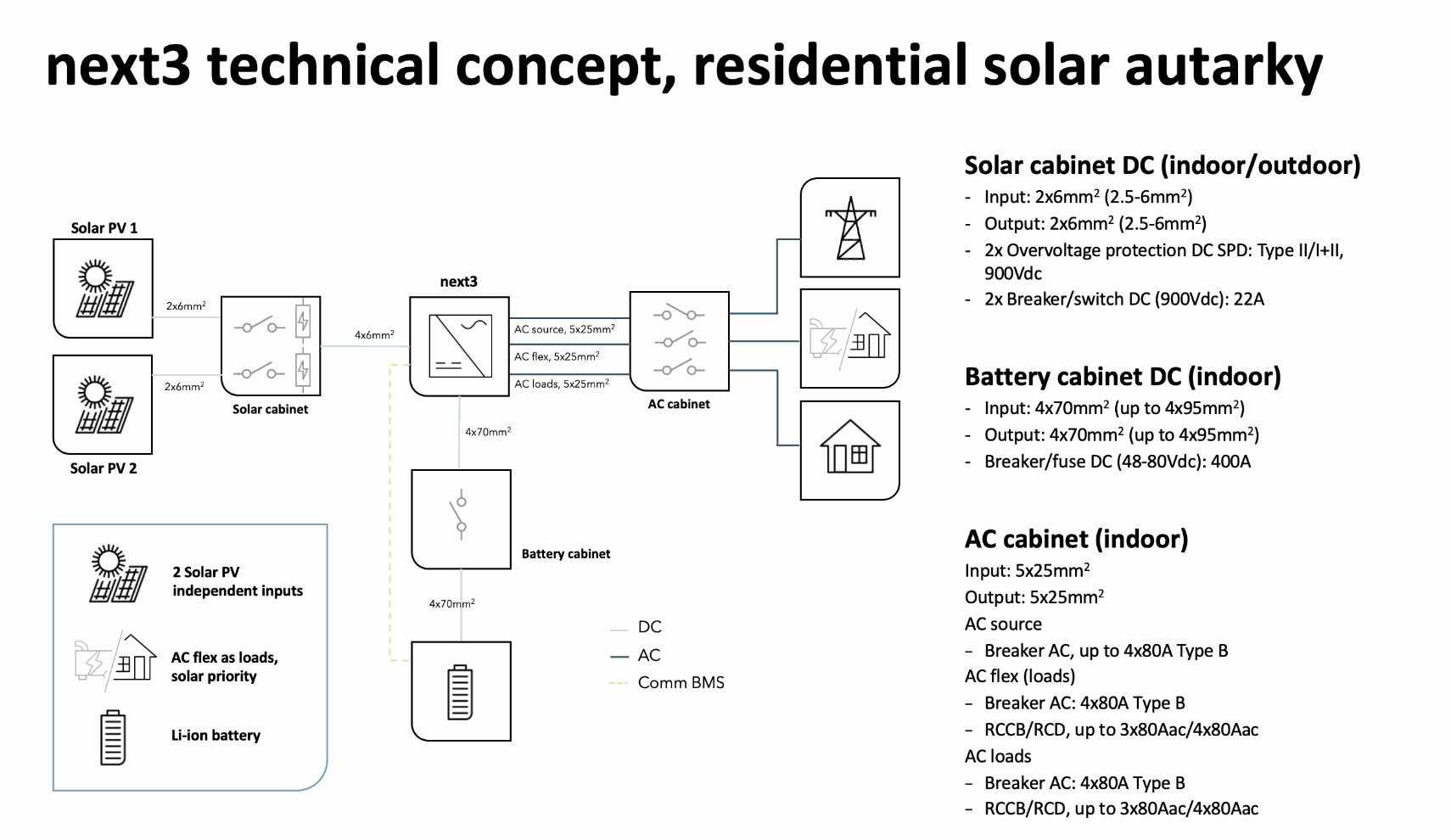
Technical concepts
Residential solar autarky
A complete energy system is based of several main elements (solar, storage, loads, sources), being our inverter charger the central element in terms of power management. We share with you an example of the elements required in a complete energy system for residential energy autonomy.