General recommendations
The connection of the next3 charger is an important step of the installation. The next3 is designed to be robust and is electronically protected against overloads, short-circuits, overheating, polarity reversal of the battery and polarity reversal of the PV.
Be aware of the following general guidelines:
- It may only be carried out by qualified professionals, aware of the rules and regulations in force. The installation must always comply with the local standards
- The cross-sections of the cables connected to its terminals must comply with local regulations even if indications are given in following chapters.
- The installation materials such as cables, connectors, distribution boxes, fuses, etc. must be adapted and must be conform to the applicable laws and regulations, specially about fire hazards.
- All cables in use should be isolated with PVC, TFE, PTFE, FEP, neoprene or polyimide. The installed cables must withstand at least 70°C wire temperature. Make sure that connections are correctly tightened and that each wire is connected at the right place.
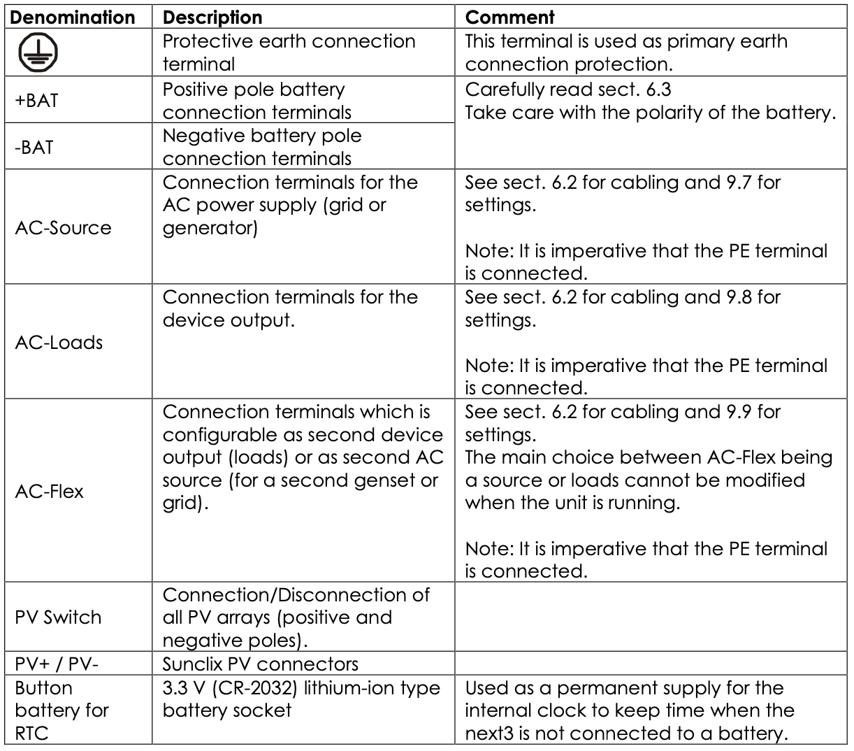
The next3 falls within protection class I. It has a PE connection terminal. It is mandatory that a protective earth is connected to the AC-Source and/or AC-Loads PE terminals. An additional protective earth is located at the bottom of the unit.
The connection compartment of the next3 must remain permanently closed while the device is operating.
Before opening, check that all voltage sources (AC, battery and PV) have been disconnected or switched off and wait for at least 2 minutes before opening the equipment. It is imperative to close the protection cover on the connection terminals after each servicing.
Before connecting or disconnecting the entry or exit cables AC-Source, AC-Loads and AC- Flex, the installer must be sure that there is no voltage present in the cables OR on the terminals.
Connections overview
Any unused cable entry on the device must be sealed to prevent any intrusion. Intrusion of small animals in the unit may cause serious damages not covered by the warranty.
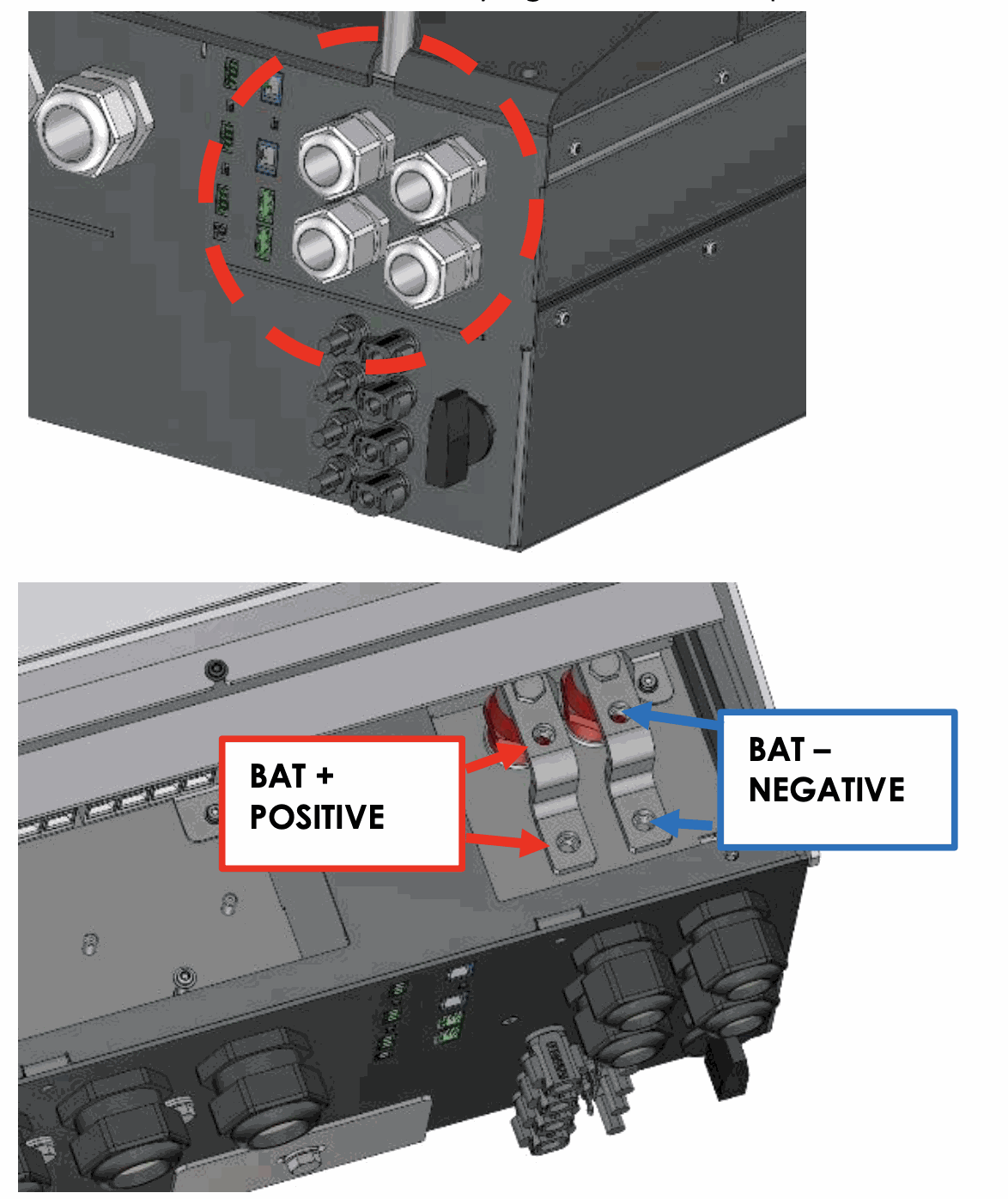
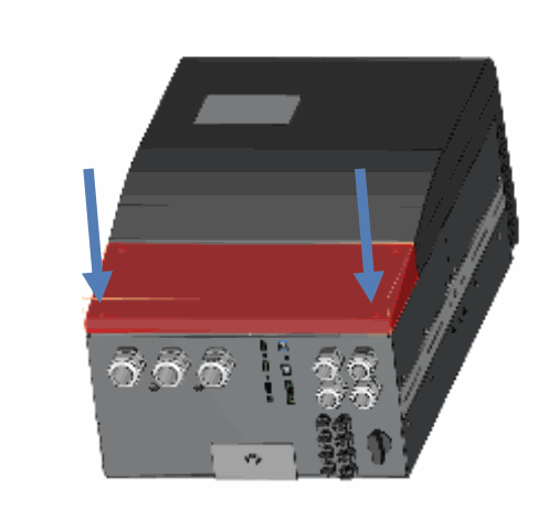
Open the connection compartment by removing front cover.
Communication and I/O connections:
See corresponding chapter for detailed wiring and protocol in use.
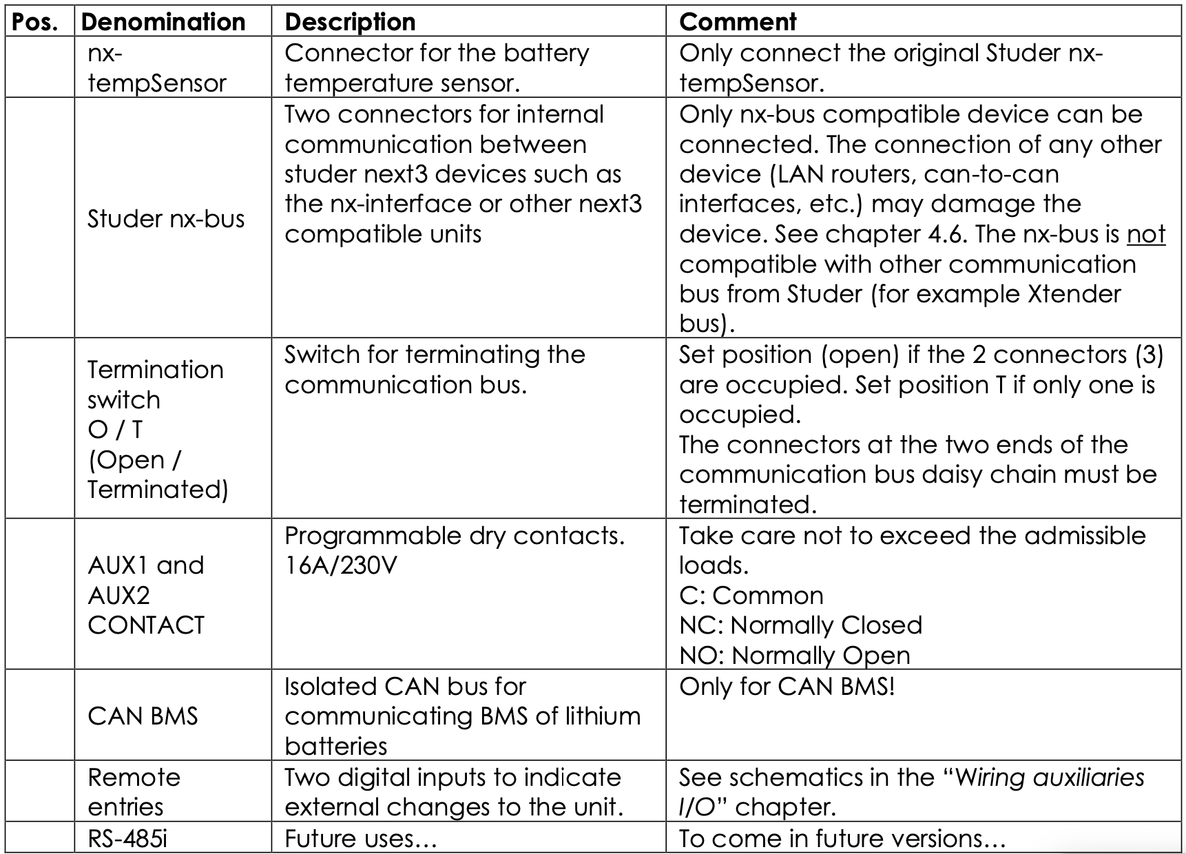
Tightening torques
The tightening torque of different connection points should be checked regularly, especially in installations exposed to strong vibrations (mobile systems, vehicles, boats, ...). The table below states the recommended tightening torques for each connection:
An annual check of all the connections tightness is recommended.
In mobile installations, the connection tightness should be checked more often.
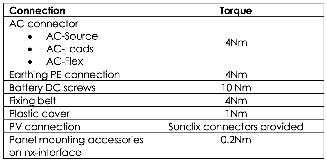
Max permissible cable cross-sections summary
The maximum permissible cable cross-section for each connection is defined by the size of the corresponding cable gland, which is indicated in the below table:
Connecting the battery
The next3 is a device wich DC (battery) connection is to be connected exclusively to a 48V battery.
Due to high power of the next3, the battery cables are separated in two entries in parallel to have a more convenient handling. The recommended battery cable size is 70mm2 for a total of 140mm2 with two cables in parallel. The maximal size is 95mm2 for a total of 190mm2 section.
Battery cables must also be as short as possible, and the cross-section must conform with the applicable regulations and standards. Sufficiently tighten the clamps on the "battery" inputs.
Battery cables must always be protected by one of the following measures:
Have a protection and disconnection device (fuse, circuit breaker) on each pole or only on the pole not connected to earth.
The protection device must be rated according to the cable cross-section but must not exceed 1.25 x next3 maximum current.
It will be mounted as close as possible to the battery. The maximum current is given with 16000/48=333Adc with factor: 333x1.25=416Adc.
Each next3 is connected directly to the battery through its own protective device (fuse or circuit breaker) and disconnection device. It should never be connected to the output of a DC voltage regulator like solar regulator, without having the battery as a buffer.
All other consumers or sources are connected directly to the battery by their own protective and disconnection devices.
For dimensioning the battery please check the dimensioning section.
Battery cable cross-section, DC protective and disconnecting devices
The battery cables must also be as short as possible. Recommended section for the nx3 battery cables is 2x70mm2 and a 400Adc protection. The recommended cable cross-sections are valid for lengths less than 3 m. Beyond this length, it is strongly recommended to oversize the battery cables (possible up to 2x95mm2 for cables connected to next3 battery poles) and consider the voltage drop in the cables. The maximal battery cable length allowed is 10m.
For safety reasons, we recommend an annual check on the tightening and corrosion of all connections. In mobile installations, the tightening of the connections should be checked even more frequently. For lead acid batteries, an individual measurement of each cell is recommended. Any divergent values can be a sign of problem.
To avoid any further loss and protection redundancy, the next3 does not have an internal fuse.
The battery cables must be protected by one of the following measures:
- protection device (fuse) and disconnection device at each pole
- protection device (fuse) and disconnection device on the pole not connected to the earth
In all cases check local regulation and normative.
Connecting the battery
Start the connection on the next3 side first, without any voltage. Keep battery poles away/ protected to prevent any unwanted contact with conducting parts.
next3 side connection
Insert the cable glands supplied on the battery cable before tightening the cable lugs. Crimp the cable lugs and fasten the cable gland on the device. Repeat this for all battery cables. Fix the battery cables to the appropriate connections "+ Battery" and "- Battery". The M8 screws must be very well tightened (10Nm).
battery side connection
Prepare the batteries for connection: appropriate battery clamps, protection device, cables in good conditions with correctly fitted clamps.
Fasten the negative cable on to the negative pole (-) of the battery and the positive cable on the open protection device.
The cable lugs must be carefully fixed and tightened sufficiently to guarantee minimum loss. Insufficient tightening may cause dangerous heating at the connection point.
During the first start of the unit, it is necessary to check that the parameter values of the next3 are consistent with the recommendations of the battery manufacturer. Non- conforming values may be dangerous and/or seriously damage the batteries.
See the chapter about programming and set the proper values at initial commissioning (with wizard on nx-interface).
Earthing of battery
One of the two battery conductors can be earthed. This may be either the positive or the negative pole as the battery is isolated from the other potentials (PV, AC). In all cases, the installation must be conform to the local regulations and usage or specific standards associated with the application.
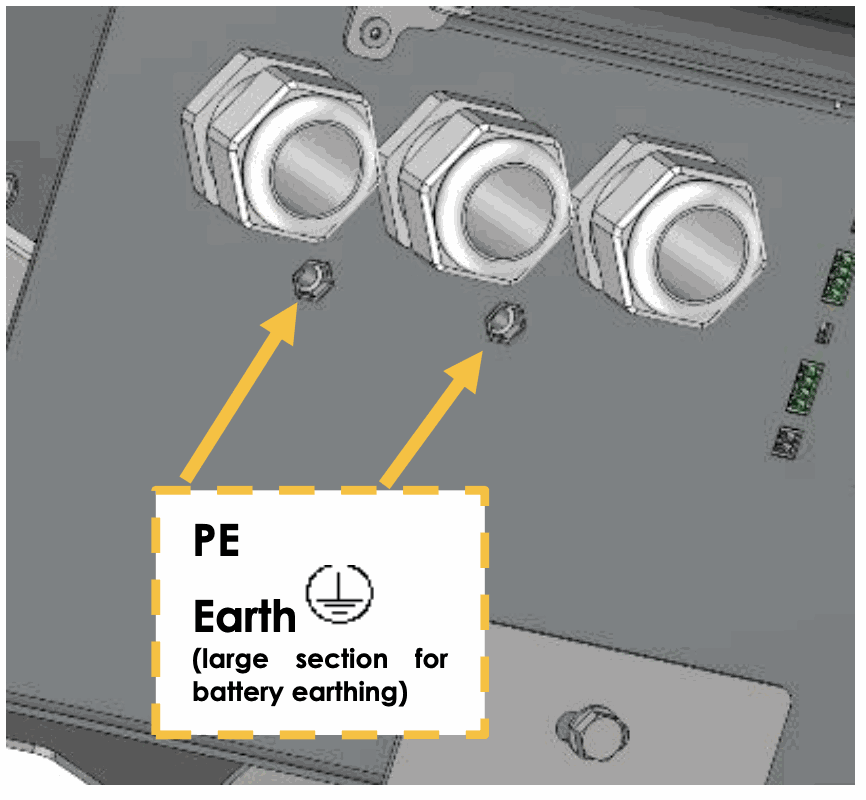
In case of earthing, the earthing conductor cross-section must at least be equivalent to the cross- section of the battery conductor. The earthing of the equipment must also adhere to these regulations. For this case, use the additional earthing screws, which are located at the bottom of the device under the AC cabling glands.
All the other earthing systems (earthing by means of a protection device, impedance, without earthing or earthed at battery positive pole) require the whole battery circuit to be protected against electric shocks.
Any accidental contact with the conductive parts of the battery circuit is to be avoided by providing a Class II protection level.
Precautions when using batteries
The batteries should only be chosen, dimensioned, and installed by qualified personnel. Lead- acid batteries with liquid or gelled electrolyte produce a highly explosive gas during normal use. Other special types of batteries present similar risks. Avoid source of sparks or fire in the immediate vicinity of the batteries. The batteries must be kept in a well-ventilated place and installed to avoid accidental short-circuits when connecting.
Never try to charge frozen batteries. When working with batteries, a second person is required to give assistance in case of problems.
Fresh water and soap must be kept close at hand to allow adequate and immediate washing of the skin or eyes affected by accidental contact with the battery acid. In the event of accidental contact of the eyes with acid, they must be washed carefully with cold water for 15 minutes. Then immediately consult a doctor.
Care is required when working close to the batteries with metal tools. Tools such as screwdrivers, open-ended spanners, etc., may cause short circuits. Sparks created by short- circuits may cause the battery to explode. Therefore, these kinds of tools must always have isolated handles and never be placed on top of a battery. When working with the batteries, all metal jewellery such as rings, watches with a metal bracelet, earrings, etc., must be taken off. The current supplied by the batteries during a short circuit is sufficiently powerful to melt the metal and cause severe burns.
Batteries at the end of their life cycle should be recycled in accordance with directives from the responsible local authorities or the battery supplier. The batteries should never be thrown into fire as they may explode. Under no circumstances should you try to take apart or dismount the battery, as they contain toxic and polluting materials. For ungrounded battery systems, always check that they are not inadvertently grounded before starting to work on the batteries.
Always carefully follow the instructions of the battery manufacturer.
A battery voltage higher than 80V can cause important damage or destroy the equipment.
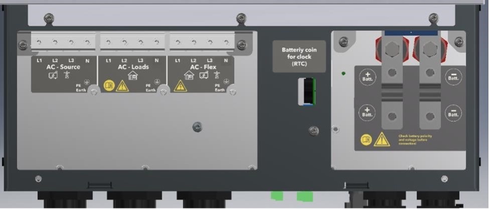
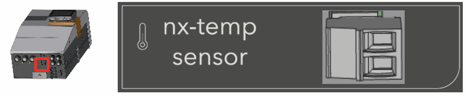
Battery temperature sensor connection (nx-tempSensor)
The operating voltages for lead batteries vary depending on the temperature. A temperature sensor is available to correct the battery voltage and guarantee an optimum charge in function of battery temperature.
The temperature range of the sensor is from -25°C to 70°C. The default temperature compensation for lead acid batteries when a sensor is plugged is -3mV/°C/cell compared to 25°C. For a 48V battery this is 72mV/°C. See the configuration section of this manual for modification of the temperature coefficients. A warning is raised at 40°C and error is raised at 55°C; those thresholds can be modified. The temperature sensor nx-tempSensor is supplied with a 10m cable and the proper male connector beside. The connection has no polarity and can be done in one or the other direction without preference. The sensor should be placed as close as possible of the battery.
The temperature sensor is automatically recognised, and the correction of the voltage thresholds applied immediately in case of non-communicating battery. If a communicating battery is used the temperature measures by this sensor is not taken into account as the temperature is directly given by the BMS. The nx-tempSensor temperature is recorded in the datalog.
Battery with communicating BMS: CAN connection
The next3 uses a CAN Bus to communicate with the BMS (Battery Monitoring System) of a lithium battery. Lithium batteries are more complex to handle compared to lead acid batteries. A BMS is responsible of cell monitoring and battery safety. The BMS knows the status of each cell, and it computes maximum charging/discharging currents and maximum/minimum target voltages. These values must be respected when the installation is working and BMS communicates to inverter/chargers the proper setpoints for proper operation.
The next3 has several CAN protocols implemented for communication with different battery management. These protocols are compatible with specific batteries.
Check the compatibility section for the up-to-date list of compatible batteries, brand and models.
Update the next3 software to have the latest communication protocol available.
Beware of the pinning order (CANH, CANL, GND) on the connector, see instruction of the BMS manufacturer carefully. An appendix about various lithium batteries is available.
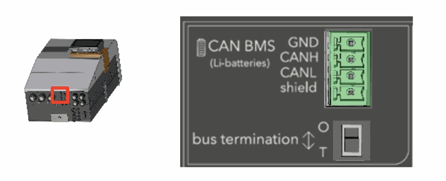
For a point-to-point connection, the bus termination should be set to T (Terminated). If the device is in the middle of a daisy chain, the termination is set to O (Open). Generally, the next3 is connected point to point to the BMS and the termination should be on T.
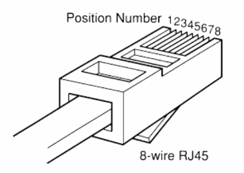
Most of batteries BMS have a specific connector for CAN connection and a specific pinning for the wiring. There is no standard. Even with a RJ45 connector, the pinning may vary. The cable must be adapted by the installer case to case. Beware of the pinning order (CANH, CANL, GND) on the connector, see instruction of the BMS manufacturer carefully.
As example here is the pinning for the CIA-303-1.
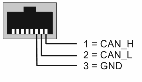
That must be wired/screwed with the provided connector:
For the specific communication connection for the compatible batteries, please check them out here.
Connecting the AC (Alternating Current)
Dangerous AC may be present on the connection terminals. Make sure that the inverter is deactivated and that there is no AC or DC voltage present on the AC terminals before proceeding with the connection.
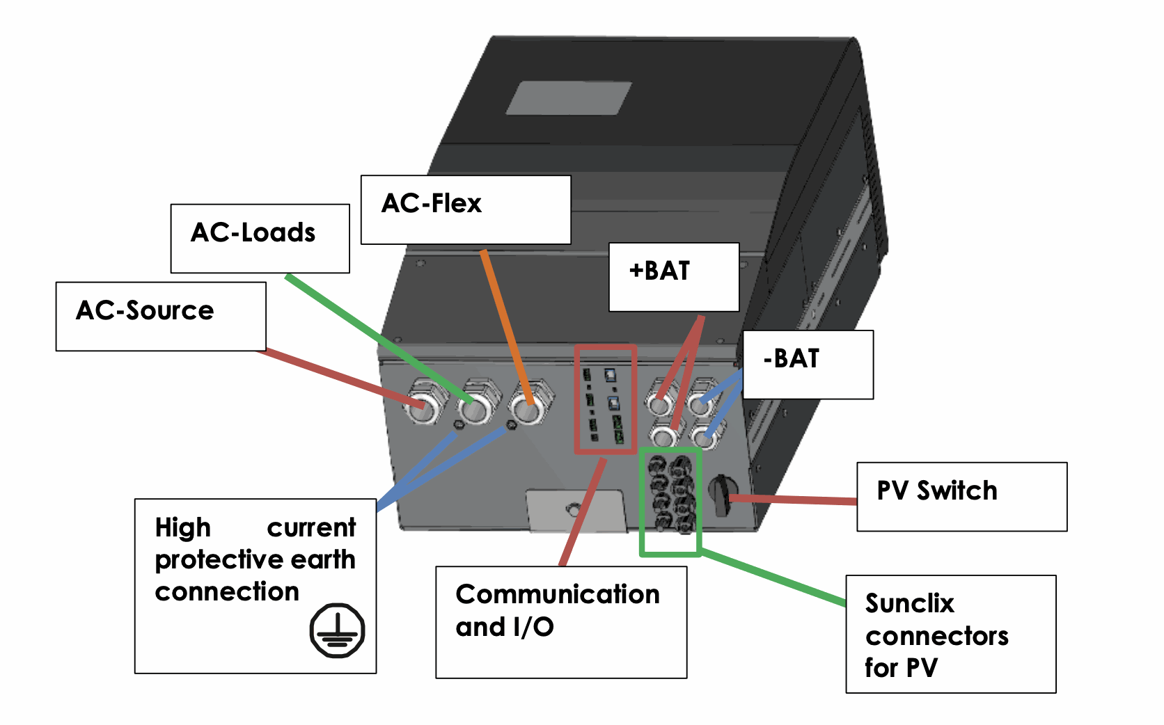
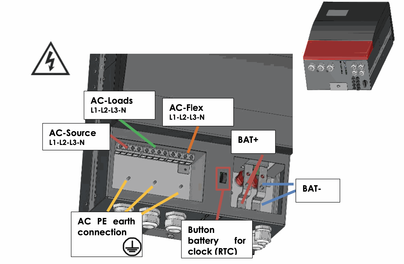
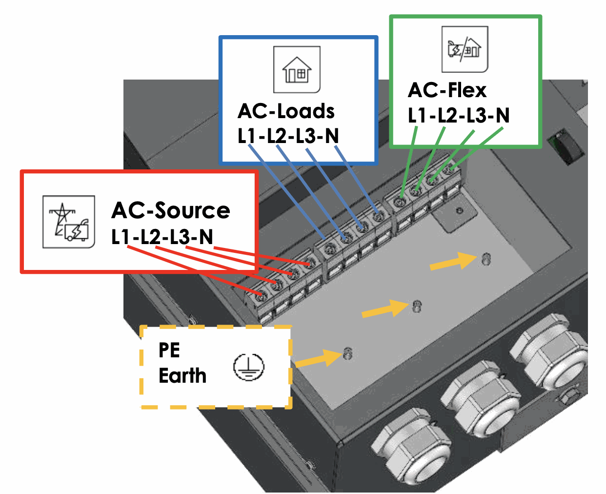
On the next3 model, remove the cover plate by unscrewing the two screws to access the AC terminals and protective earth. The connections inside are shown on the figure below.
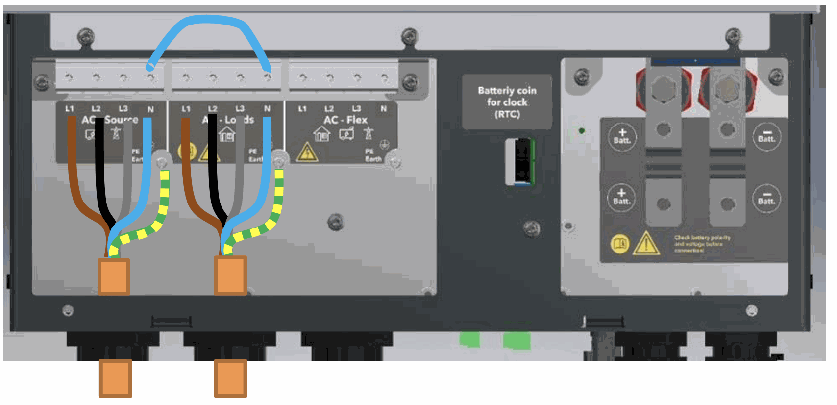
There are 3 AC connections:
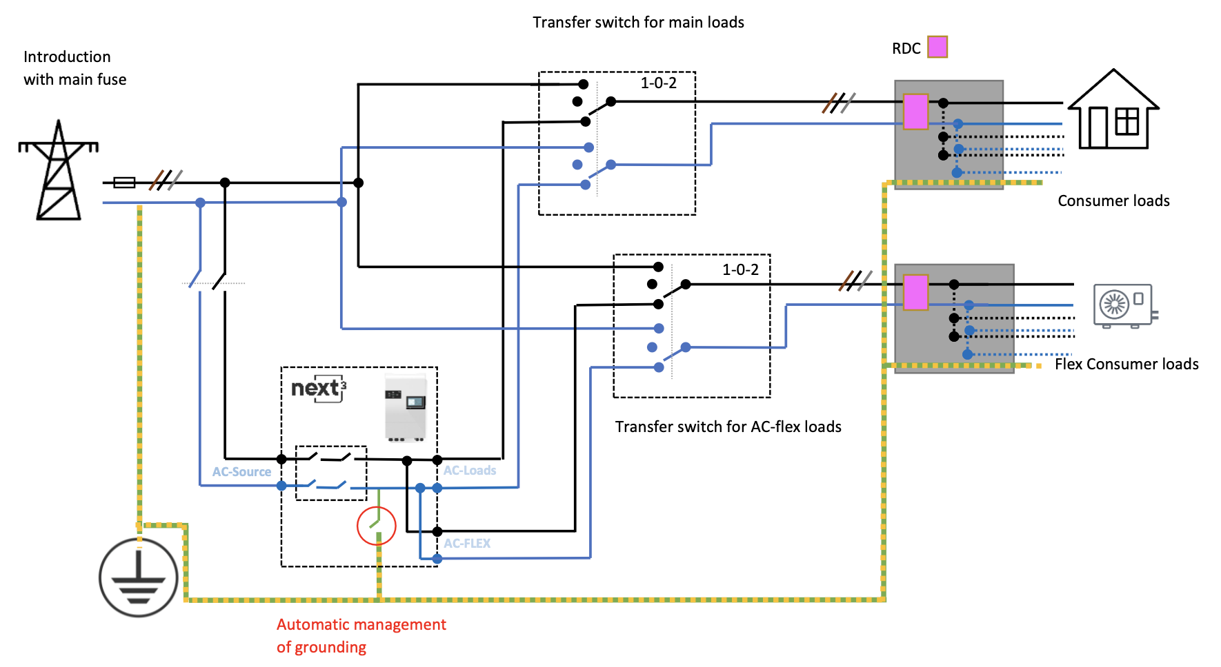
- AC source: connection for the main AC source. A grid or a generator. This input has double security relays for disconnection according to safety and grid code requirements like VDE-0126 and others. In case of grid connection, always connect the grid to AC-Source.
In offgrid, a single-phase source may be used and connected to the L1 of the AC-source. For example, for a small single phase genset as a backup. - AC loads: connection for the loads, that are supplied by the inverter. The 230 V and 400V consumers must be connected on the "AC-Loads" connection terminals with the wire cross- section conforming to the standards regarding the rated current at the next3 output.
- AC flex: this is a configurable connection to be connected to loads or to a genset. The choice of configuration is done at the setup of the system during the Wizard procedure. The AC-Flex configuration is fixed and cannot be changed anymore in operation for security reasons.
On models without transfer (nx3-16000-48 and -s) there is no AC source and no AC flex connections.
Refer to the general schematics (block diagram) at the beginning of this chapter for a better understanding.
The next3 terminals are marked in the following way:
- N = neutral
- L = lines (L1, L2, L3)
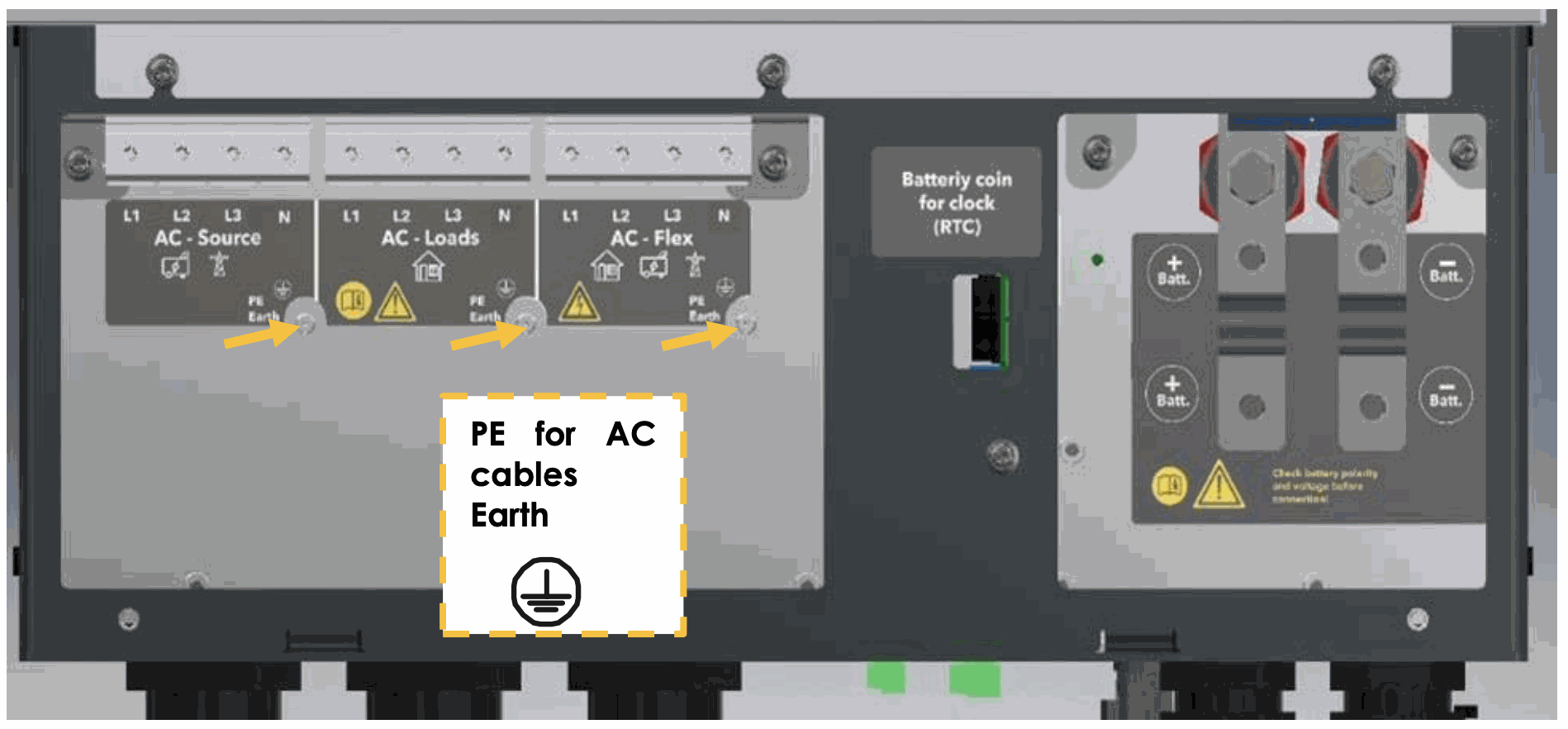
 = protective earth (connected to the enclosure of the device).
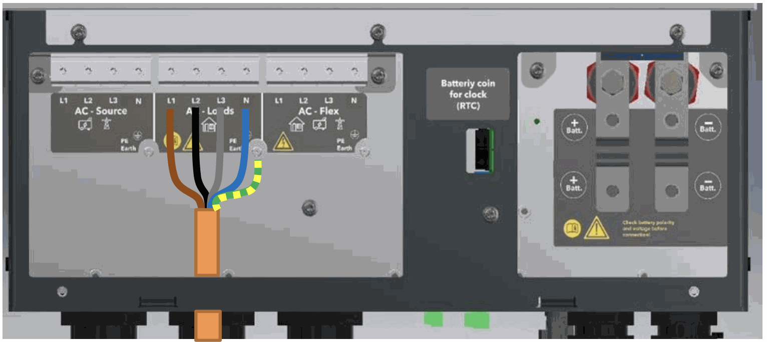
Example of connection for AC loads
Insulation tests:
At commissioning of an electrical system, insulations tests are performed on the wiring (in some countries, depending on local regulation). It is performed applying high voltages on the cables and measuring the leakage current. This must be done without the next3 in the loop. Overvoltage surge protections included in the next3 will invalidate the tests.
Insulation between circuits and the ground is tested in factory for every next3 unit manufactured according to the device IEC/EN 62109 and IEC/EN 62477 safety standards.
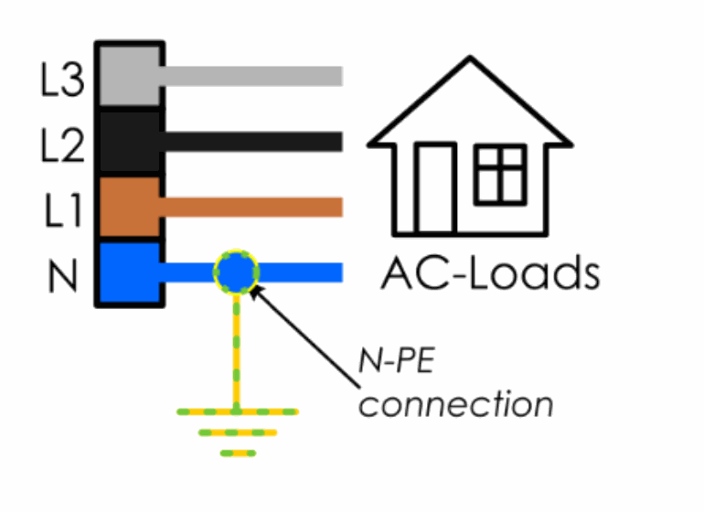
AC neutral and earthing system
The next3 is a unit with protection class I, which is intended for cabling in a grid type TT, TN-S or TNC- S. Its metal case must be earthed. The earthing of the neutral conductor is carried out at a sole installation point, upstream of the RCD circuit breaker (in domestic application, generally type A, 30 mAac).
The neutral insulation to the earth is checked by the device and errors will be raised by the next3 if the measurements doesn’t correspond to the settings of the device.
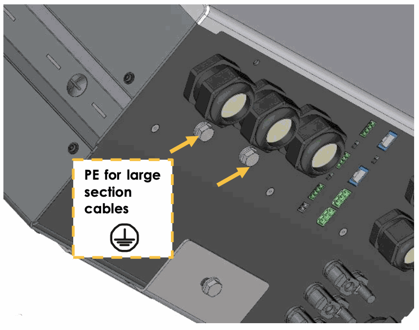
The next3 case and/or the PE connector, depending on the local installation rules, have to be connected to earth. The PE cross section must be as big as the cross section of the line or neutral conductor, but the minimum cross section must be at least 10mm2.
= protective earth (connected to the enclosure of the equipment).
In any case, the protective earth must be connected in accordance with local standards and regulations in force. The protective earth of the equipment must be connected at least to the protective earths of all the Class I equipment after and before the next3 (equipotential connection). The information, notes, recommendations, and diagrams reported in this manual are examples and must in any case be adapted to local installation rules. The installer is responsible for the conformity of the installation with the local standards in force.
An additional earthing terminal is present under the AC-cables glands at the bottom of the unit. It can be used instead of a connection on the input terminals of the device, particularly when cable cross-sections used at the output do not allow the use of a five-wire cable (lines L1 L2 L3, earth and neutral) through the conduit glands of the connection cables of the input and output (AC-SOURCE, AC-LOADS and AC-FLEX), or when the earthing of one of the poles of the battery. PE required using same or greater cross-sections than the battery cable when the battery is grounded.
Stationary installation and neutral continuity
In a stationary installation where the neutral is connected to the earth at a single installation point upstream of the next3, the standard case for the next3 is to use an automatic connection of the neutral output line of the inverter to the earth when operating in island mode (Neutral-Earth is in mode Offgrid Self-Managed). In case of doubt, wire the earth properly and use this default mode.
It is also possible to carry out a connection of the neutrals to preserve an unchanged earthing system downstream, independent of the operating mode of the next3. This is called “Solid Neutral” mode.
It may not be accepted for security reasons. Please check your local installation rules. This configuration is not recommended by Studer.
Example of solid neutral connection inside of the connection box:
Safety is guaranteed by the equipotential bonding and by any RCD circuit breakers placed downstream.
This solid neutral connection is not permitted if a socket is installed upstream of the next3 (typically in mobile application). It is not possible to mix the configuration of solid neutral and self-managed programming in the case of use of a grid and of a genset.
See the earthing relay configuration in the system configuration. The description of the earthing errors are done there.
Mobile installation or installation connected to the grid via plug connector
When the input of the device is connected directly to the grid via a plug, the plug must remain accessible.
The connection between the neutrals upstream and downstream of the next3 is not permitted in this configuration.
In the absence of voltage at the input, the neutral and live are interrupted, thereby guaranteeing complete isolation and protection of the cabling upstream of the next3.
The earthing system downstream of the next3 is determined by the upstream earthing system when the grid is present. In the absence of the grid, the earthing system downstream of the inverter is in isolated mode. An automatic connection with an internal relay can be programmed with settings.
This connection type guarantees the optimal continuity for supplying the next3 loads. The first isolation fault will not lead to an interruption in the supply.
If the installation requires the use of a permanent isolation controller this would have to be de- activated when the TT network is present at the next3 input.
All sockets and protection class I devices connected downstream of the next3 must be properly connected to the earth (earthed socket). The cabling rules above remain valid, including in installations, in all cases where the next3 input is connected to the grid via a plug connector.
next3 system without transfer
On models without transfer (nx3-16000-48 and -s) there is no AC-Source and no AC-Flex connections. These models do not have programmable earthing relay either. Thus, user must guarantee complete isolation and protection of the system. In such installation it is recommended to bond directly the neutral to the earth at one point in the system.
RCD breakers
For people safety, RCD breakers should always be installed. This requires a proper grounding of the neutral to work properly.
As the next3 can work in offgrid mode and interrupts the live and the neutral wires, the earth automatic connection to neutral (offgrid self-managed setting) should be used. The RCDs are placed after the next3 in the distribution box.
In case of a bypass use with both AC-Load and AC-flex bypass, there must be at least 2 RCD as the live wire are independent.
Commissioning AC
At commissioning various tests are performed by the electricians (according to the local rules).
Insulation tests
At commissioning of an electrical system, insulations tests are performed on the wiring (in some countries, depending on local regulation). It is performed applying high voltages on the cables and measuring the leakage current. This must be done without the next3 in the loop. Overvoltage surge protections included in the next3 will invalidate the tests.
The insulation between the circuits and ground is tested at the factory for each next3 unit manufactured in accordance with the safety standards IEC/EN 62109 and IEC/EN 62477, before the final installation of the surge protectors. The manufacturer Studer Innotec therefore guarantees the correct insulation of the unit to earth in this case. The installer must check the wiring without the presence of the next3.
Short circuit current and overload behaviour
In island operation (offgrid), when the inverter is not connected to the grid but operates on battery power, the output impedance of the next3 device is so that it cannot pass the standard short-circuit current tests carried out at the commissioning of an electrical installation.
Nevertheless, in case of a fault (short circuit, overload) the current is electronically limited by the device. When a short circuit occurs, it is detected, and the device stops automatically. Safety is ensured in this case. The short-circuit current of the next3 in island mode is 45Arms. In grid connected mode, the short-circuit current is given by the grid as inside of the next3 is just a contactor.
A next3 device detects a short circuit when the voltage falls below 50% of the rated voltage at maximum current limitation, the device will then shut down within 0.5 seconds. For a limited overload, when the voltage drops to less than 80% of the nominal voltage during a current limitation, then the device stops after 3 seconds. By default, the device tries to restart after 1 second for a maximum of 3 times. The number of attempts is reset to zero after 30 seconds of normal operation.
All these parameters can be set in "Expert" mode. Studer Innotec recommends leaving the default values.
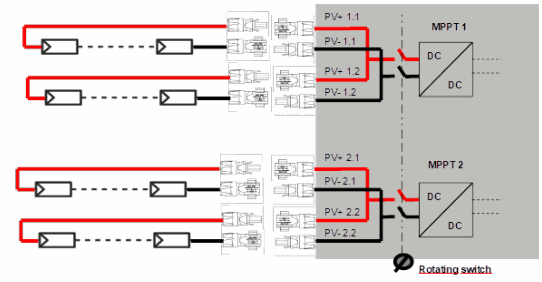
Connecting the PV generator
The next3 has an internal solar charge controller made of two independent MPPTs. Each MPPT can support up to 20Adc of photovoltaic (PV) current in operation. For this reason, each MPPT has 2 inputs and up to 4 strings can be connected to the device. The two inputs of the top (MPPT1) are connected internally, as well as the two at the bottom (MPPT2). The rated current of the PV generator can be higher as the next3 limits with electronic control the maximum taken from the generator in any case. In any case the maximum short-circuit (Isc) current is 27Adc.
The next3 solar input is intended to be connected exclusively to a source like a photovoltaic generator, excluding any other energy source.
The next3 is designed for PV generators supplying up to 900Vdc. This voltage is dangerous for human beings.
During the installation or the maintenance of the system, it is mandatory to make sure that no dangerous voltage may surge in the system. The disconnection device must be open and secured against any accidental reclosing.
PV modules must have a Class A rating according to IEC 61730.
When the photovoltaic array is exposed to light, it supplies a d.c. voltage to the next3.
For dimensioning the PV please check the dimensioning section.
The two MPPT with each 2 connections are situated below the next3.
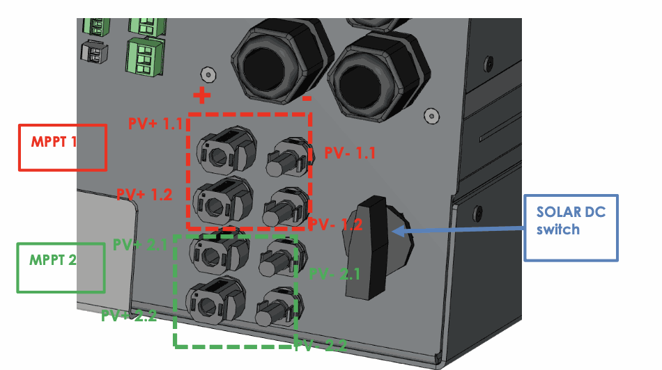
The PV+ is situated left and the PV- is situated right. Check carefully the indications written on the NX3 in case of doubt.
For one MPPT, if two strings are connected in parallel, they must be composed of the same types of modules, and the same number of modules, to avoid voltage mismatch and production losses.
Earthing of PV
The MPPT topology is non-isolated for best efficiency, so the poles of the PV must not be grounded. The electronics was designed to avoid fluctuating voltages on the PV poles. In operation, there is a constant voltage on PV+ and PV- compared to the ground referential. This avoids leakage current through the parasitic capacity between cells and ground and therefore avoid problems with RCD breakers (return current default).
The PV input of the next3 is non-isolated, which means the PV+ and PV- must be floating (similarly to the majority of Transformer Less, TL, solar inverters). The PV must not be grounded. Accidental grounding will be detected and cause a stop of the next3 inverter. The frame of the PV modules should be grounded.
PV modules must have a Class A rating according to IEC 61730.
As the Open Circuit voltage (Voc) of the panel is above 60Vdc (in all the temperature range), the whole solar system must be installed according to protection class II. Use proper connectors and cables for all the solar system, as requested by local regulation.
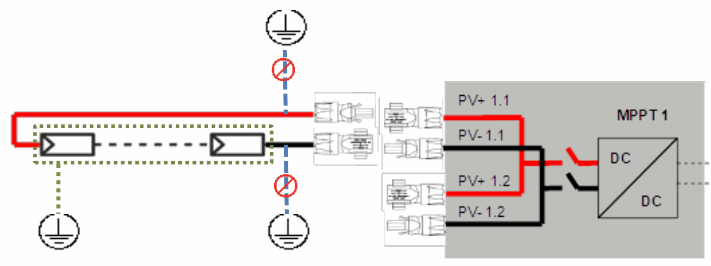
Never ground PV+ or PV-. Ground the PV modules frames
Cables and cross-section
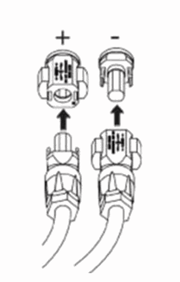
The next3 is build from factory with Phoenix Sunclix connectors for the PV inputs of the MPPTs. There are 4 pairs of Sunclix connectors provided with the unit to assemble on your PV wires arriving to the unit. These connectors can be assembled without special tool. A flat screwdriver is necessary to decouple the connected once enclicked.
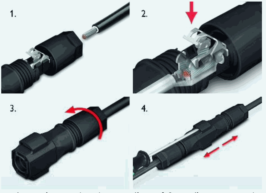
The minimal section for cables in Sunclix connectors is 2.5mm2. Sunclix connectors are rated: 2.5mm2: 27Adc / 4mm2: 40Adc / 6mm2:40Adc. We advise you use a 4 or 6mm2 cross section to reduce the cable losses in the system even if a 2.5mm2 cross section would have been enough. In any case follow local regulation for cable sizing regarding the short-circuit current (Isc) of the PV generator and length of cables.
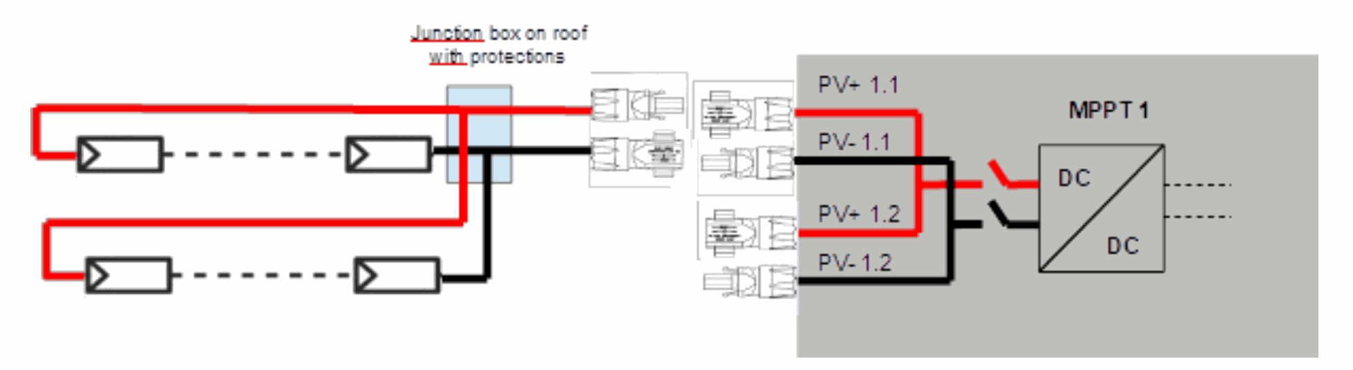
If you wish to install two PV strings in parallel for one MPPT, this can be assembled as well out of the Next3, for example in the junction box on the roof. This can minimize the number of cables used. The parallel strings can be connected together before the next3 solar entry as long as the maximal short-circuit current (Isc) of 27Adc is not reached.
Protection devices
Wiring protection devices (fuses, circuit breakers) connecting the PV generator to the next3 must be installed in accordance with local standards and regulations in force. Special rules are existing for fire hazard and access to switching devices by firemen.The internal PV switch of the NX3 disconnects all poles between the PV generator and the charge regulator.
PV modules are often exposed to stormy weather. It is highly recommended to install lightning protection. This is mandatory in some countries. Please see local standards and regulations in force.Lightning protection
According to the installation site, it is highly recommended to develop a protection strategy for your installation. The strategies depend on various factors specific to each site; we recommend therefore a professional approach to this issue.
The next3 has internal protections against lightning by means of surge protection devices. These devices have an energy dissipation capacity limited to 3,5kA (8x20 μs) which guarantees a certain protection level but are not a total protection against lightning. Furthermore, these protections are for single use. Therefore, in the event of a lightning strike where these surge protections are hit, you'll have to send the unit for repaire. They cannot be replaced nor repaired on site.
Damages due to lightning often result in significant costs (full replacing of the printed circuit board, PCB) and are not covered by Studer Innotec’s warranty.
Contact a specialist on surge protective strategies to check how you can best protect your system in all inputs/outputs (AC and DC).
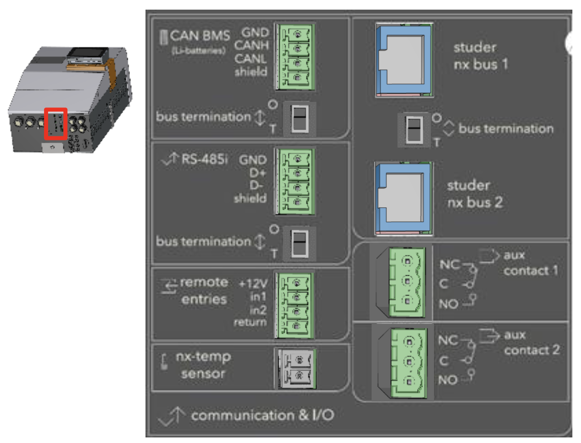
Connecting the communication cables
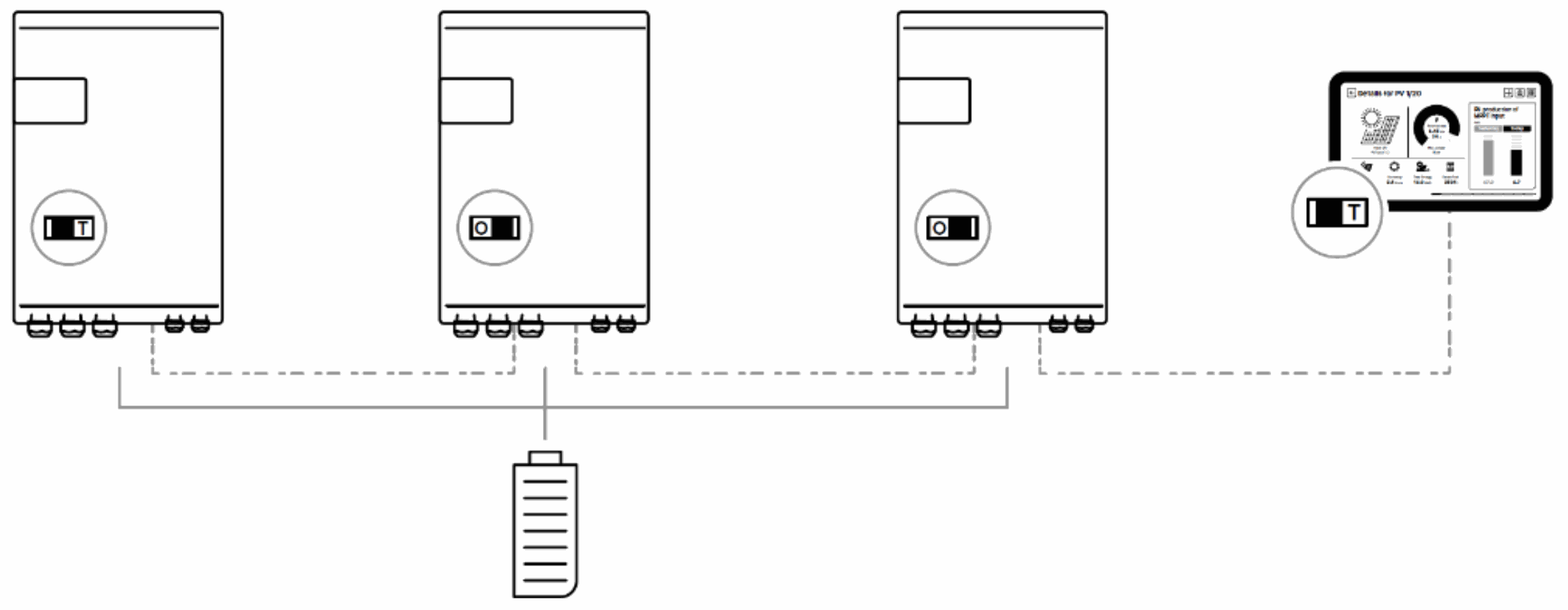
The Studer nx communication bus is used to interconnect next3 inverters in the case of a multi-unit application, to connect the nx- interface or to connect other types of devices with communication compatibility.
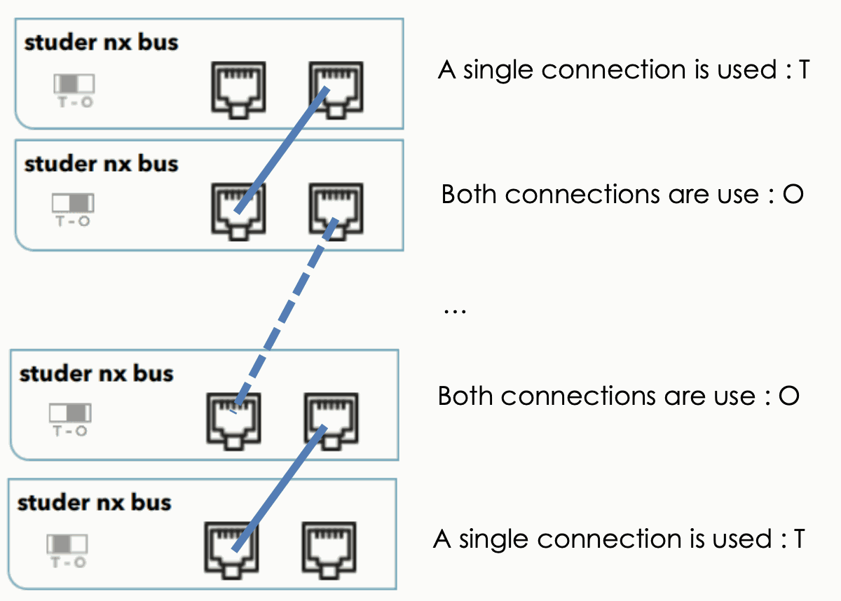
The NEXTs are equipped with a pair of RJ45/8 connectors that allow information transfer via a communication bus in between next3 devices or accessories that use the proprietary protocol of Studer-Innotec. In this network, all parties in the network are connected in daisy chain.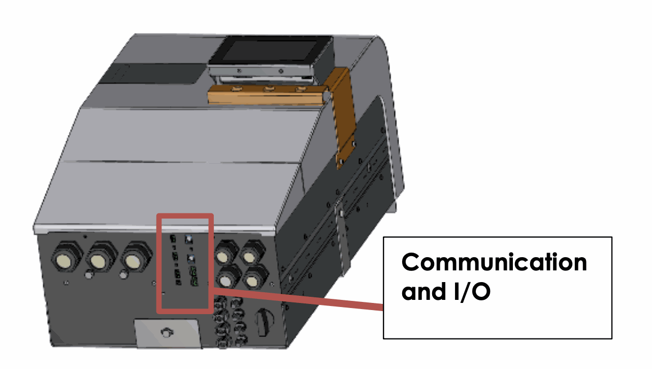
The cables for Studer nx bus are straight ethernet of category 5 exclusively with 26AWG wire size (power supply through cable). They are provided by Studer or you can buy your own as long as it follows these requirements. The total length of the communication bus cable between all units must not exceed 75 m.

The switch for the communication bus termination remains in position T (terminated) except when both connectors are in use. In this case, and only in this case, it must be placed in the O (open) position. If one of the two connectors is not in use, the termination switch will be in position T.
In a system comprising a single next3, the connection of the nx-interface or nx-gateway units may be conducted without stopping the next3 (hot plug).
These connectors must be used only to connect a compatible next3 accessory, excluding any other type of connection such as LAN, Ethernet, ISDN, etc.
The next3 communication is not compatible with other Studer communication. It is not compatible with Xtender devices and it must never be directly connected together.
Any unauthorized connections could cause the destruction of the devices.
A standard configuration with 3 next3 and one nx-interface is shown here below.
When connecting one device with other compatible devices using the same communication bus, it is highly recommended to make a software update of all components in the system to guarantee their proper compatibility/functionalities. Therefore, before starting the setup of the device, download the latest software version from our website: www.studer-innotec.com and copy it to a USB key. The update is made by the remote control nx-interface.
Connections to the nx-interface
The nx-interface can be fixed on the nx3 with the dedicated support or hanged remotely in a place closer to the end-user of the system. It must be connected to the studer nx-bus.
The total communication cable length in a system is 200m. The nx-interface is powered through the cable, so his type must be ethernet of category 6 exclusively with 24AWG wire size (power supply through cable).
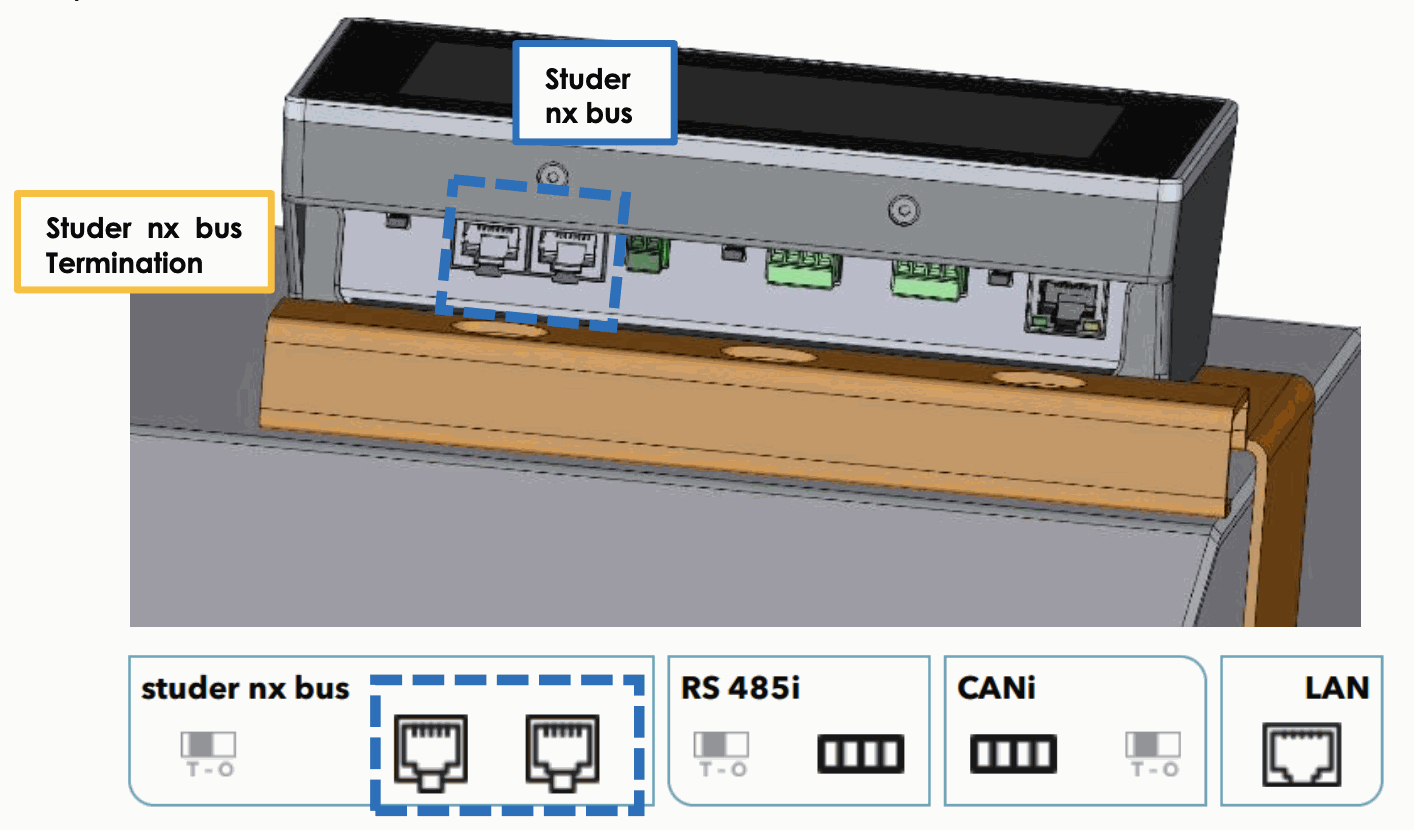
The state of the Studer nx bus termination on the nx-interface can be seen on the screen, this is only for the connectors situated on the nx-interface.
Note: the RS-485i and the CANi on the nx-interface are unused for the moment.
Connecting to Internet
The connection to your LAN and internet is done exclusively in the nx-interface on the Ethernet port.
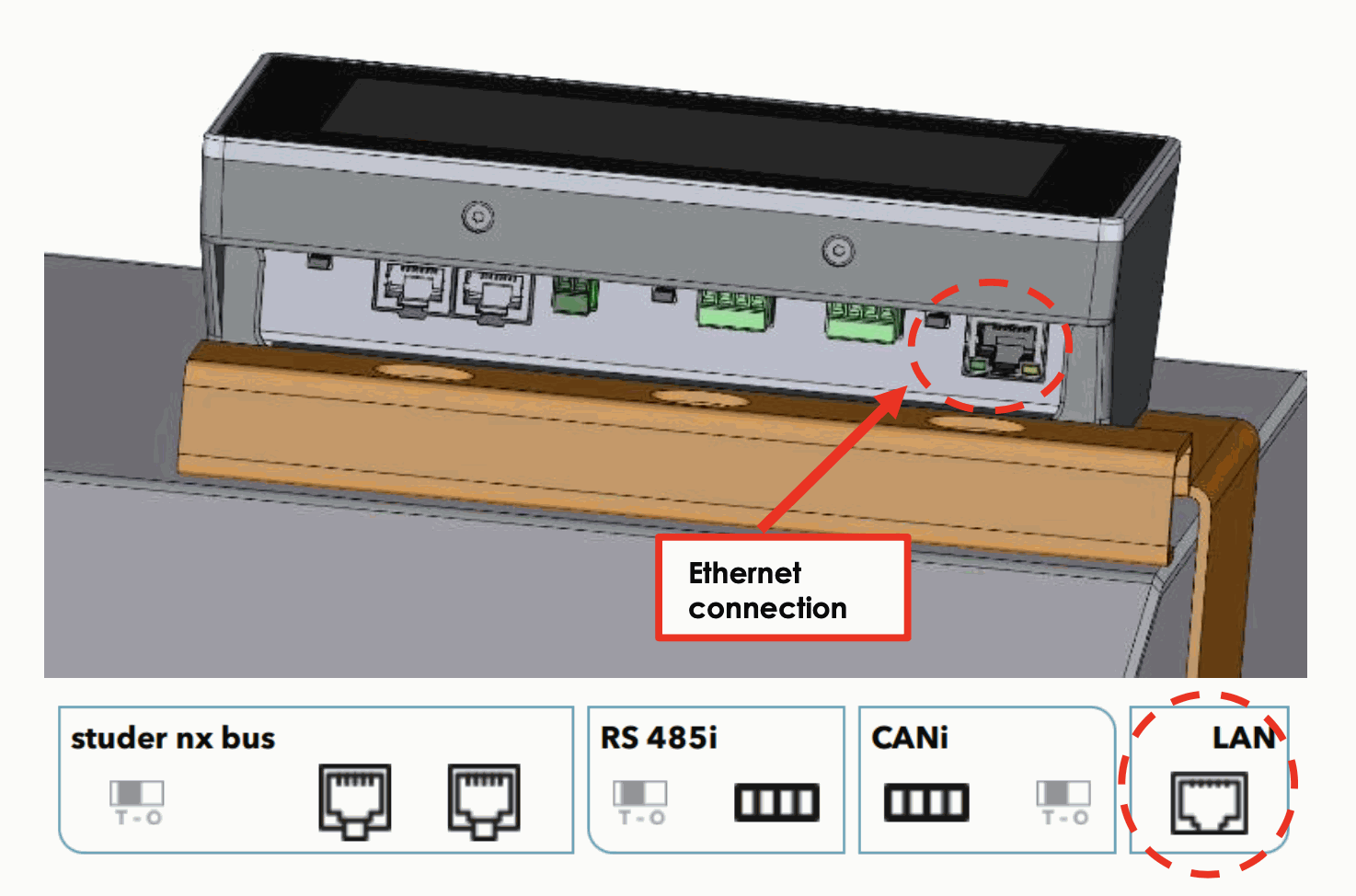
Differentiate carefully the ethernet connection with the two led on the low side of the connector.
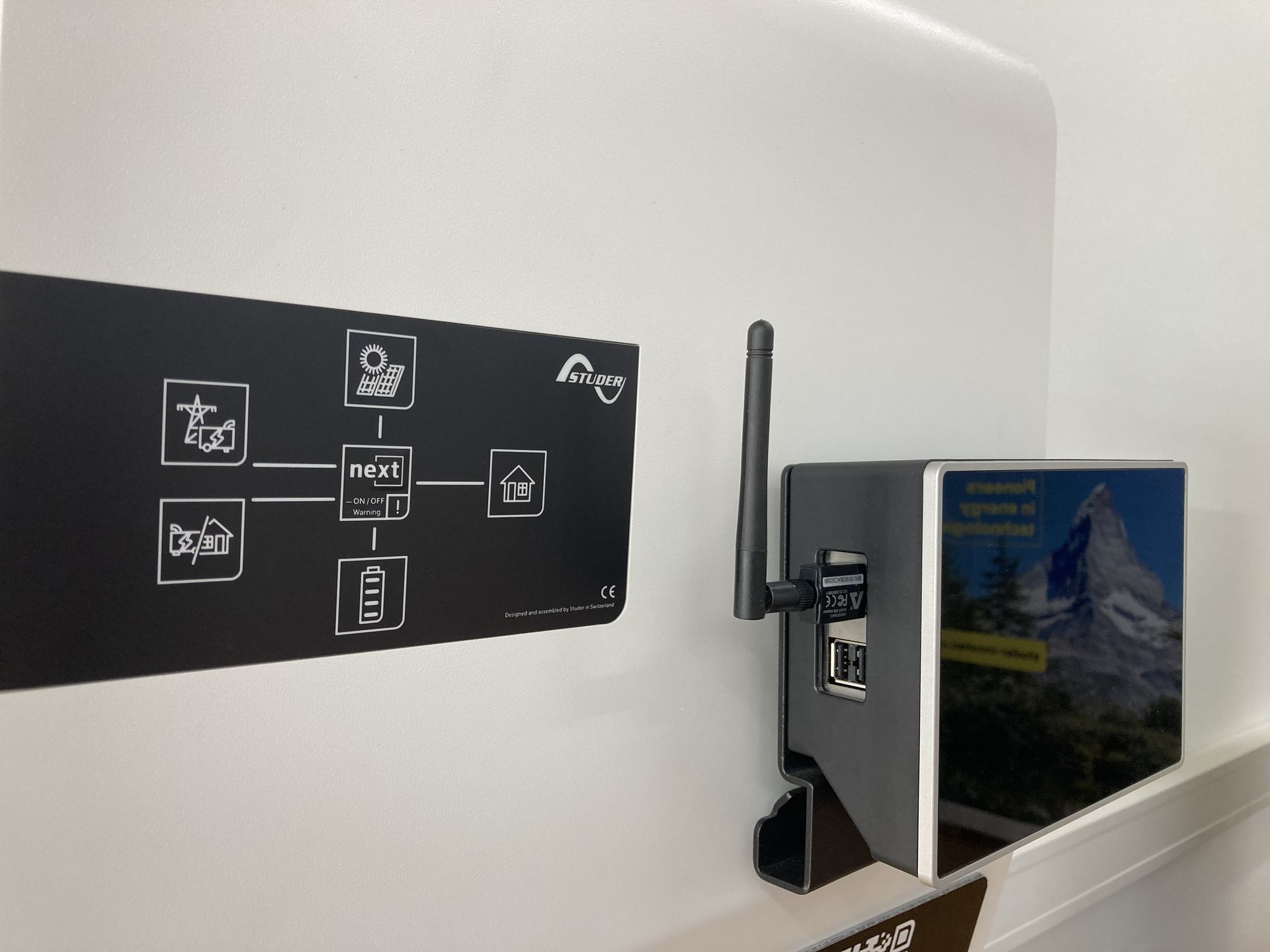
The second way of connecting the next3 to the internet is the use of Wi-Fi.
This is done with the Wi-Fi USB stick (nx wifidongle) provided by Studer-Innotec. Use only the official Wi-Fi USB stick provided by Studer-Innotec because the nx-interface needs to have the proper driver. There is little chance that a third party Wi-Fi stick works properly.
For the LAN connection, there is no setup to do. For the Wi-Fi connections, you must select the Wi-Fi network and enter your password.
The internet connection set up is described in the programming chapter of this manual. See the chapter “configurations” for the setup of the internet connections.
In remote area, you can find your own GSM 3G/4G/5G router (not provided). Studer-Innotec is not responsible for the proper operation of those devices and of your internet connection.
Wiring auxiliaries i/o
Auxiliaries are all located at the bottom of the next3.
Auxiliary contacts
There are two reversing contacts that are potential-free available in nx3 unit.

Various settings are available to give activation conditions to each contact. To program functions to these contacts, please refer to the chapter about the configuration of the next3 and the section about the auxiliary contact in this manual.
Wire the C (common) in any case and the second position in function of your application and your settings. In relax state, there is a contact between C and NC (Normally Closed). An activation gives contact between C and NO (Normally Open) and disconnect C and NC. The representation of the contact near the terminals corresponds to the status of the contact when not activated.
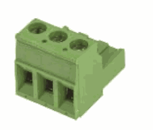
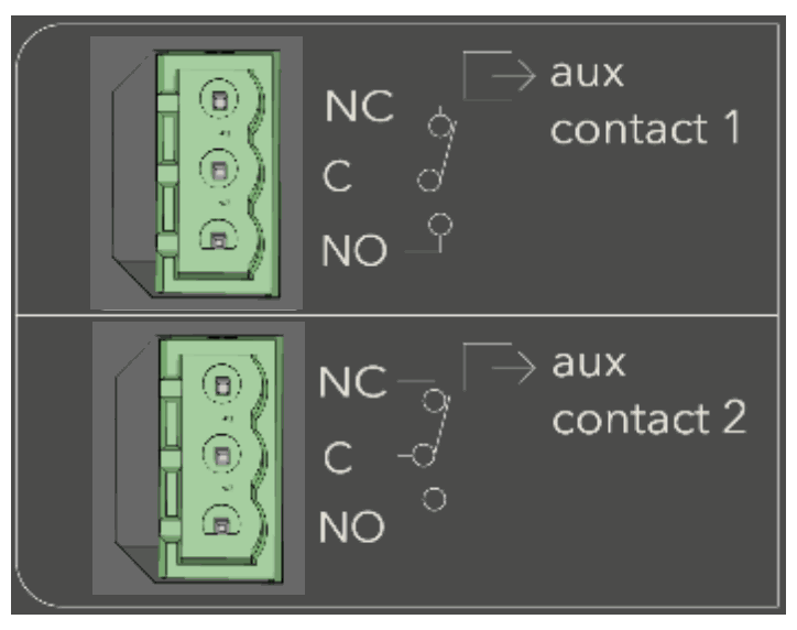 Male connectors are provided with the NX3. The admissible currents and voltages for these contacts are 16 A: 250 Vac/24Vdc or 3 A: 50 Vdc max.
The connector has a male and female parts. Double-check the correct pinning when plugging the connector on the nx3.
Command inputs
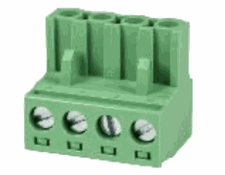
IN1 and IN2 are inputs that can be active with a 5 to 60Vdc voltage to the return reference. The nominal voltage is 12V. The 4 poles connector is supplied with the nx3. Double-check the correct pinning when plugging the connector on the nx3.
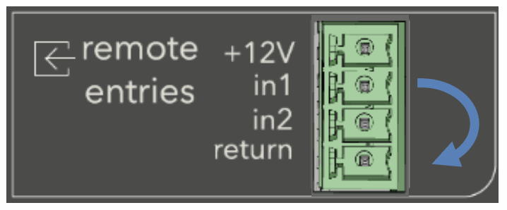
A +12Vdc supply is available on the connector for the use of dry contacts. Don’t use it for other purpose than the activation of input entries. The current is limited. External 12Vdc can be activated/deactivated with settings in the device menu (on nx-interface).
The various possibilities are given with the schematics below.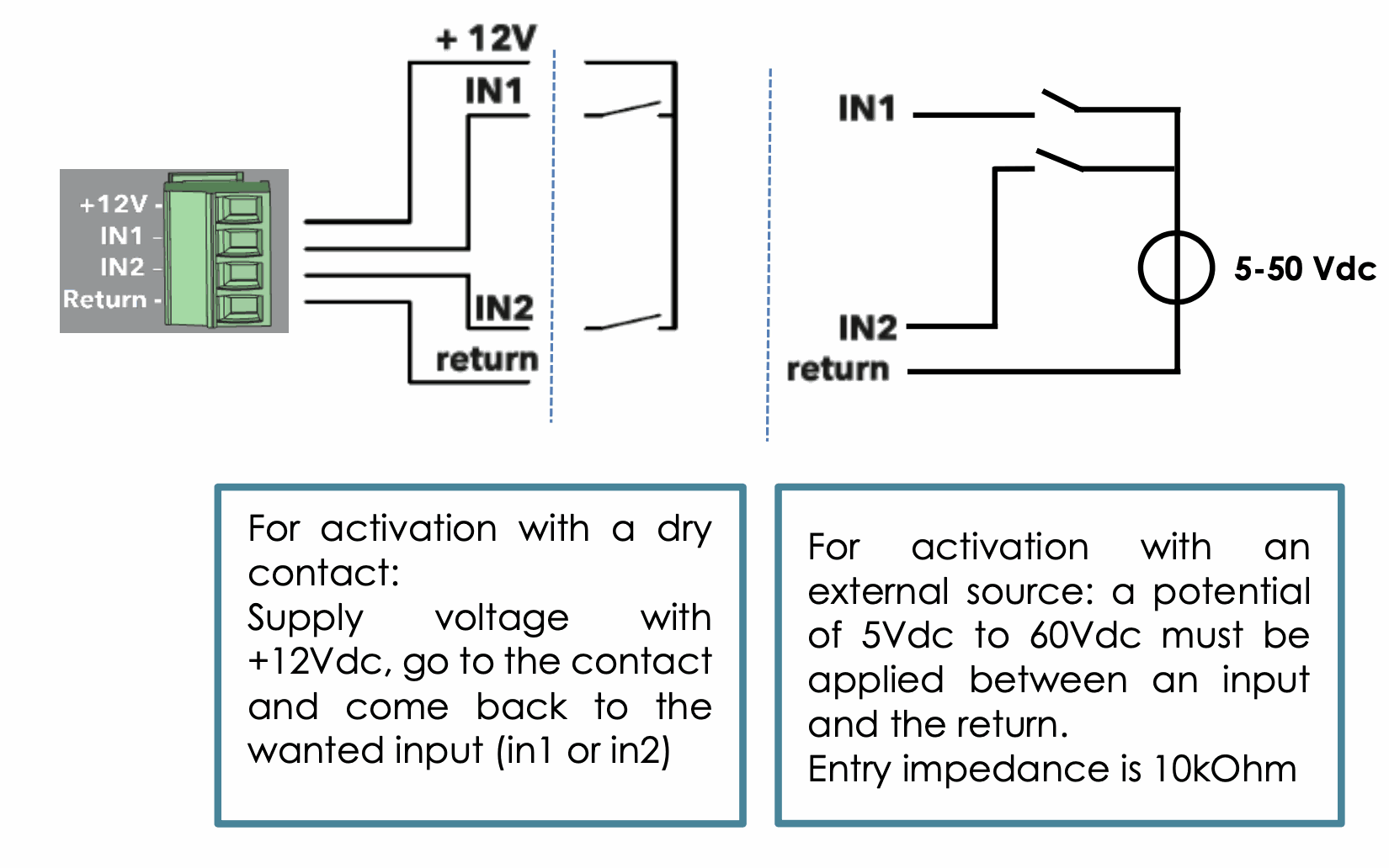
RS485i
A communication to accessories will be available in the future, keep updated...
Modbus to read values and change settings on the next3 is implemented on the nx-interface, not on this connection. See the chapter about the nx-interface.
Multiunit configuration
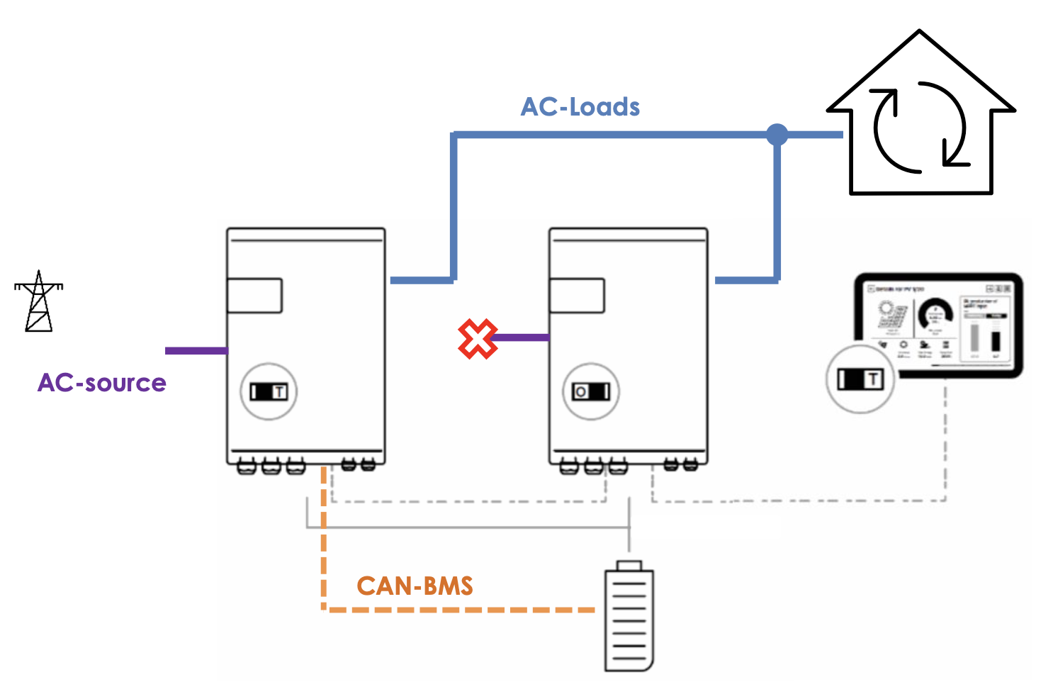
Up to two next3 units may be used together in parallel. They are connected on the same battery bank or on 2 separate battery banks to create a high-power inverter-charger system.
Two units of next3 can work in parallel creating an 32kVA inverter with an 80A transfer (55kVA). This is available from the software version 1.2.0.0 and higher.
In multi-unit systems, next3 are interconnected via a communication bus that uses the “Studer nx communication bus”. Units should be close to each other (in the same room).
The following points must be followed for the wiring:
- Each device must have the same software version, updates are available on the Studer website and this manual under the section updates
- Use only one nx-interface per system. The system will not work properly with multiple nx-interface communicating at the same time of the bus.
- A reconfiguration of the system with the wizard is mandatory when you add new elements to the system.
- All the AC-loads of a system must be connected in parallel, for each respective phase (through a distribution panel for example).
- All the AC-Flex as loads must be kept separated. The different AC-Flex can be programmed separately.
- Only one AC-source will be used in a system. There is an identification process during the configuration of the system with the nx-interface (wizard). That means the maximum transfer is 80A and 80x230x3= 55.2 kVA. The compatibility is only between next3 units. Don't mix with other Studer Innotec products like the Xtender. This will not work and probably damages the devices.
Battery management
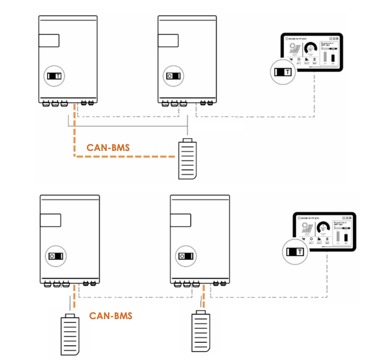
In a multiunit system, one battery with BMS is communicating with one next3, they must be physically connected with the CAN-BMS cable, and it must be paired properly during the wizard process.
It is allowed to have one common battery or multiple batteries.
See the configuration section of this manual for details.
In multi-unit systems, the charge/discharge current of each unit is automatically chosen by the PFD (Power Flow Dispatcher, which is a patented control algorithm). Just give properties of each battery during the wizard process.
The used rules are:
- The charge/discharge is distributed proportionally to each battery capacity.
- The charge/discharge limits are used independently.
- Each SOC is managed independently and limits are respected (if they are not at the same level at start per example or bad configuration was done).
Example: two next3 are in parallel and only one has solar connected to its MPPT entries. In that case the two batteries are charged anyway, proportionally to their battery size. The energy flows through the AC-Loads common connection.
Extension of an exisiting installation
It is possible to extend an existing installation by adding one similar next3 units in parallel. The software compatibility of the new and old units is mandatory.
Equipment belonging to the same system must be operating with the same software version. Download the latest software version from the Studer's website and update the software for all units of the system independently before commissioning.