Introduction
One next3 inverter is enough to supply up to 16kVA for 30 minutes to a three phased load (3x 5.3kVA).
To power larger systems, there are two possibilities:
- Split the loads and power them with multiple independent next3 systems.
- Connect multiple next3 in parallel that will work together as a single larger inverter with synchronization.
This second case is described in this application note.
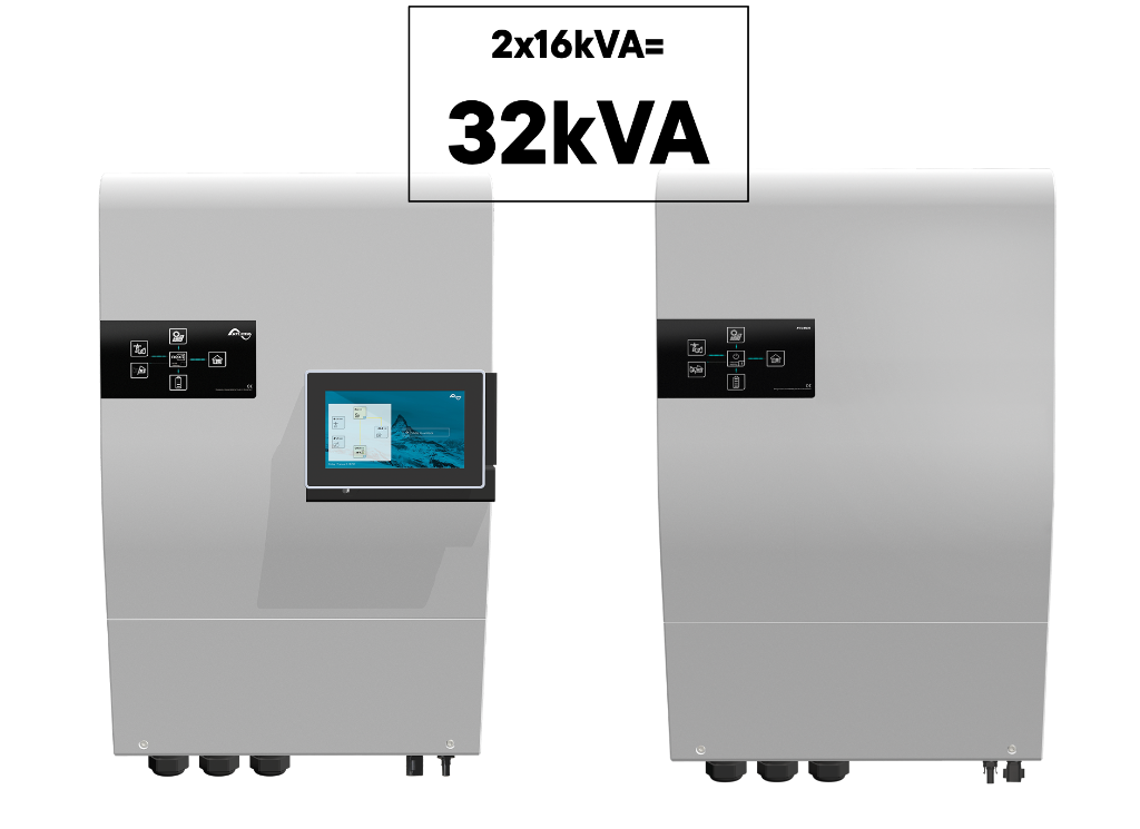
Two units of next3 can work in parallel creating a 32kVA inverter with a 80A transfer (55kVA). Three units of next3 can work in parallel creating an 48kVA inverter with an 80A transfer (55kVA).This is available from software version 1.3.0.0 and higher.

General system design
Up to three next3 units may be used on the same battery bank or on 3 battery banks to create a high- power inverter-charger system.
The following points must be followed for the wiring:
- In multi-unit systems, next3 are interconnected via a communication with “Studer nx communication bus”.
- Units should be close to each other (in the same room).
- Each device must have the same software version, available on the update section.
- The nx-interface is mandatory for configuration.
- All elements must be connected together and powered before the initial configuration. All elements must be clearly identified during the configuration with the wizard.
- Use only one nx-interface per system. The system will not work properly with multiple nx-interface communicating at the same time on the bus.
- A reconfiguration of the system with the wizard is mandatory when you add new elements to the system.
- All the AC-Loads connections of each next3 units of a system must be connected in parallel, for each respective phase (through a distribution panel for example).
- All the AC-Source and AC-Flex ports must be kept separated. The purpose of each port is chosen during the wizard.
- All the AC-Flex ports configured as FlexLoad must be kept separated. The different AC-Flex can be programmed separately.
- Only one AC-Source connection for the grid (if available), and one AC-Source or AC-Flex for the genset (if available) will be used in a system. There is an identification process during the configuration of the system with the nx-interface (wizard). That means the maximum transfer is 80A and 80x230x3= 55.2 kVA.
- The three next3 work as one in a system, except for:
-
- The PV inputs are independent.
- The AC-Flex as load can be programmed independently, they must not be wired together.
- The AUX relays and CMD IN are independent.
- The compatibility is only between next3 units. Don’t mix with other Studer-Innotec products like the Xtender. This will not work and probably damages the devices.
- In many countries, the official metering of solar installation change of category above 30kVA and required a different scheme. Be sure to respect the local regulations for this point.
Communication between the units and identification of the units
The Studer communication bus is mandatory between the units and the nx interface.
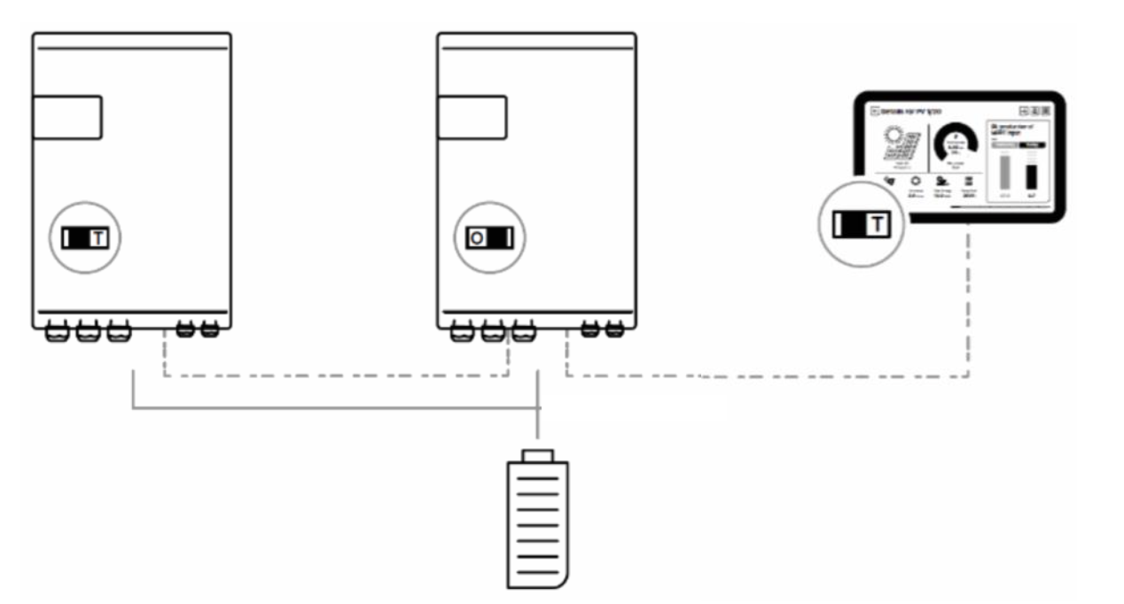
Take care of the bus termination that is O (Open) in the middle of the chain and T (Terminated) at the end of the chain. This must be set properly before powering the system with the battery. It will be checked later during the wizard.
When starting the system, the list of devices is done. Check the presence of all of them during the wizard process.

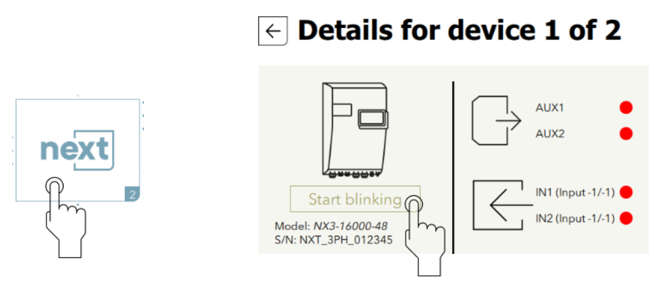
During the wizard and later in the system menu it is possible to make all the LEDs blink for a clear identification of the unit (which one is device 1 and which one is device 2, ...).
Battery setup
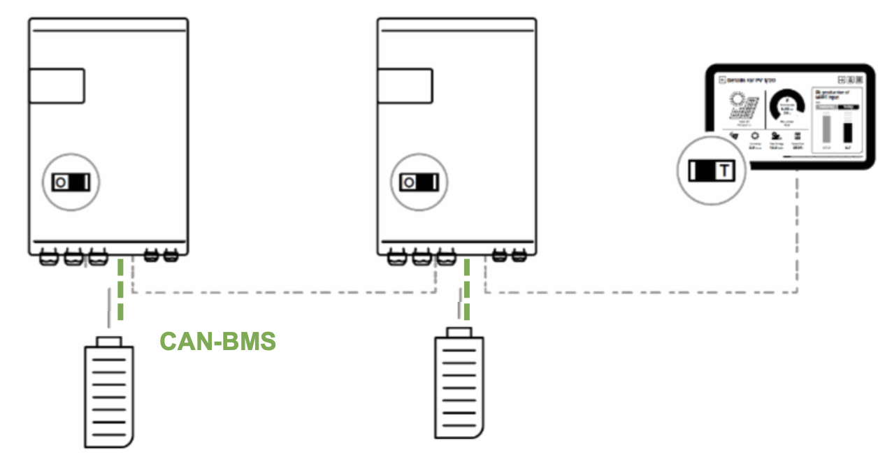
In a multi-unit system, one battery with BMS is communicating with one next3, they must be physically connected with the CAN-BMS cable, and it must be paired properly during the wizard process.
It is allowed to have one common battery or multiple batteries.
With one common battery, the can-BMS is linked to one next3 only. It must be identified and configured during the wizard process.
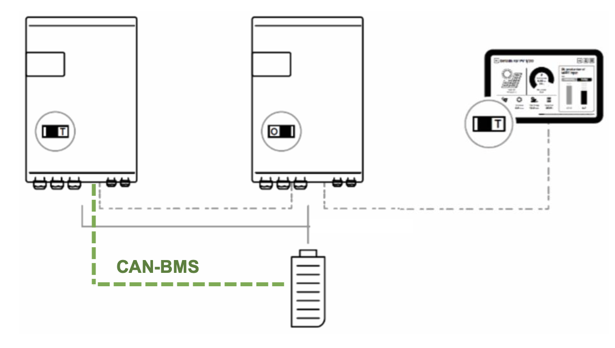
Don’t mix the communication bus of the batteries with the nx-bus. The communication with am BMS must be done with the battery wired to the same next.
The communication bus to the battery BMS, the battery DC connection and the nx-bus are isolated from each others. There is no special requirement for the connections of multiple batteries. Per example, the minus (or plus) can be common, but this is not required. Each pole can be grounded or left floating. The installer is not constrained by the next3 but must respect the installation rules for his type of application.
With lead acid batteries, each next must have its own temperature sensor.
In a multi-unit systems, each next3 is connected to a common battery bank using its own protection device. All other DC consumers or sources must be connected directly to the battery using their own protection device.
In a multi-unit systems, the carge is synchronized, the charge current of each unit is automatically chosen by the PFD (Power Flow Dispatcher, which is a patented control algorithm). Just give the properties of each battery during the wizard process
The possible number of batteries are automatically proposed up to the number of batteries.

Here the proper identification of which battery is on which inverter is done. It is especially important if you have batteries with different capacities.
Here is an example with 3 units connected to 2 batteries:

Rely on the blinking of LEDs when you select one unit. Then enter the batteries properties on each dedicated screen:

Be precautious not to mix the various battery pack.
4.1 Energy management of batteries
In multi-unit systems, the charge/discharge current of each unit is automatically chosen by the PFD (Power Flow Dispatcher, which is a patented control algorithm). Just give the properties of each battery during the wizard process.
The use rules by PDF are:
- The charge/discharge is distributed proportionally to each battery capacity
- The charege/discharge limits are used independently
- Each SOC is managed independently (if they are not at the same level at start for example).
Example: two next3 are in parallel and only one has solar connected to its MPPT entries. In that case the two batteries are charged anyway, proportionally to their battery size. The energy flows through the AC-Loads common connection.
The batteries will be managed in function of their nominal capacity given during the wizard.
Per example with two batteries, one of 200Ah and one of 400Ah, the large battery will give 2 time more power than the small one.
The configuration of each battery can be changed individually by accessing it from the dedicated screen of each battery. It is possible to have different strategies for different types of batteries mixed. This is an open possibility, but it may become difficult to understand what happens in the system and predict how the system will age.
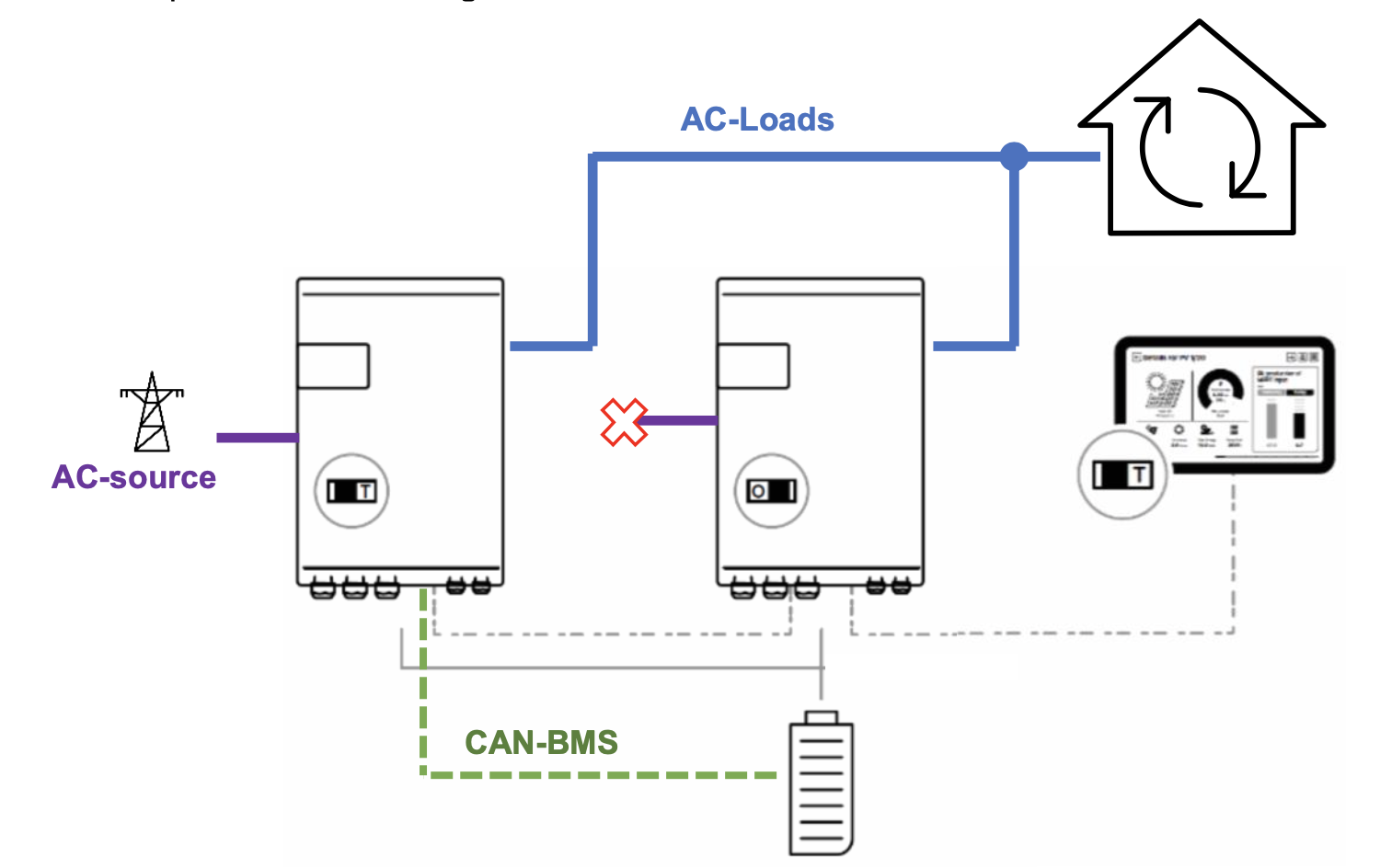
AC-Source setup: grid and genset
There is only one grid and one genset connection in a system. The different AC-source of each next3 must be kept separated.
Below is the example for the standard grid-connected case for two units.
And for three units:

During the wizard, the proper unit that is physically connected to the grid must be selected.


A similar selection process must be performed with the use of a genset. When using a genset at the same time as the grid, it is advised to use the AC-source of the second inverter. One is connected to the grid and one to the genset.
That way all AC-Flex are available for flexible loads.
The wizard automatically proposes the free ports of the device:


This case with the grid and a genset in the system is presented below:

Specific settings for multi-unit systems
With the nx-interface or other interfaces available for programming, it is possible to access the settings and information of individual element of a multi-unit system.
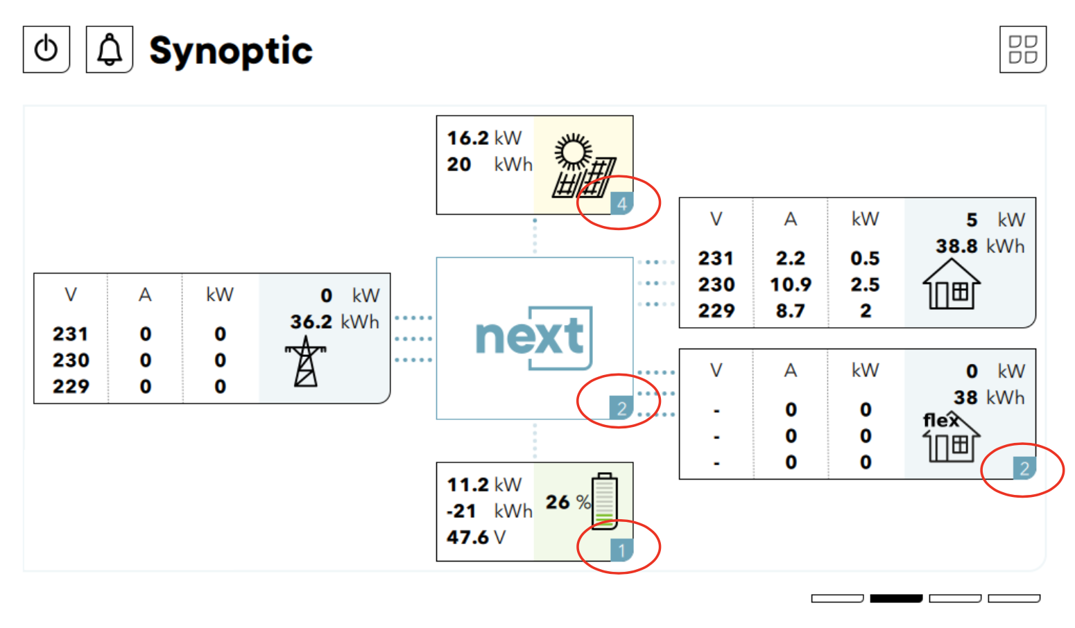
The number of units can be seen on the synoptic.
In the example below there are 2 next3 units, connected to 1 battery. There are in total 4 strings of solar (2x2). There is only the grid and then the 2 AC-Flex connections are configured as Flex-Loads.
Then the access to individual elements can be done with the swipe. Per example below when there are two batteries:
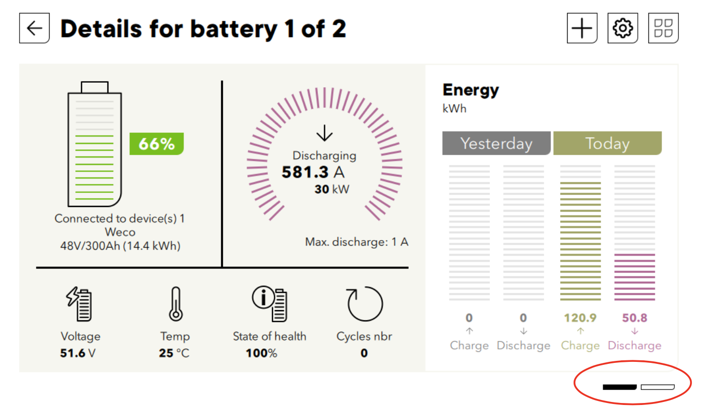
In that case if the settings menu is entered with  , the modifications will apply only to the battery 1.
Specific addressing on Modbus
The multiple devices can be addressed individually with the MODBUS.
Each parameter/setting/information is identified in the Studer world with its ID and the SECOND number gives the instance of the same group.

If several objects of the same type are present in the installation, such as two Batteries for example, the second is addressed with x.2.y.z.
For MODBUS communication this ID must be translated into the register number at a given address. The list of registers for each group/type of object/element is given in the Next Modbus appendix. To address a second instance of a group simply use an address offset of +1. Several device addresses are available for each device of an object:

For example, if two batteries are available, the first one will have the first MODBUS device address defined for the battery group and the second one will have the address. With the example above, ID 1.2.2.2 is the register
Please see the documentation in Modbus section and the appendix “Technical specification – Next Modbus appendix vX.Y.pdf” available there to get the full list of Modbus register.
Extension of an existing installation
It is possible to extend an existing installation by adding one or several similar next3 units in parallel. The software compatibility of the new and old units is mandatory.
Equipment belonging to the same system must be operating with the same software version. Download the latest software version from the Update section and update the software for all units of the system independently before commissioning.
For the extension of a battery pack, follow the recommendation of the manufacturer. Very often it is not allowed to put old and new batteries in parallel.
Conclusions
It is possible to have many next3 in parallel. From version 1.3.0.0 up to 3 units are possible, opening possibilities of systems up to 45kVA nominal and 48kVA 30minutes.
The installer should take care of wiring, especially wire sizing that should cope with large currents. There is only one critical point to respect: the AC-port connection should always be common as all devices work together as a single inverter.
Then the paralleling is quite simple from the point of view of the commissioning with the wizard.
- Be sure that all elements connected and are seen in the same system on the communication bus
- Identify correctly which next3 is on which battery when there are multiple batteries.