Handling and storage
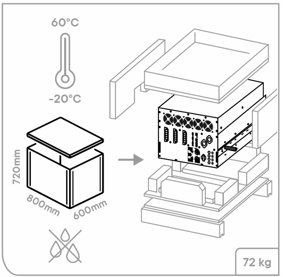
The weight of the next3 with the package is about 72kg. Use an appropriate lifting method as well as help from a third party when installing the equipment.
The equipment must be stored in a dry environment at an ambient temperature between -20°C and 60°C. Store it in the location where it is to be used a minimum of 24 hours before commissioning to avoid thermal shocks and condensation problems.
Dimensions
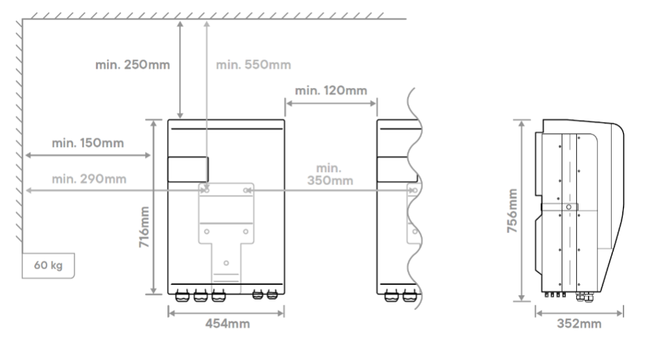
Dimensions of the wall mounted next3
The next3 must be installed vertically. Distances of at least 12cm around the units and 25cm above the equipment are required to guarantee adequate ventilation (see mounting section of this manual).
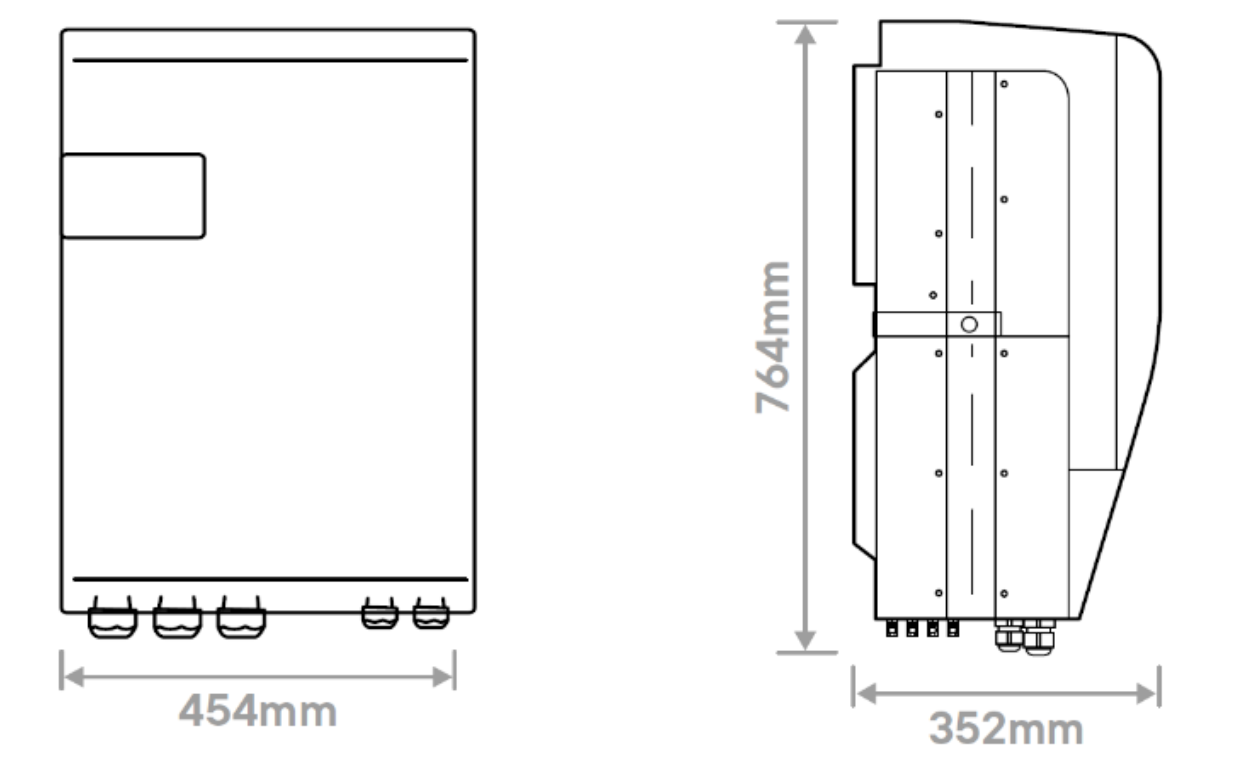
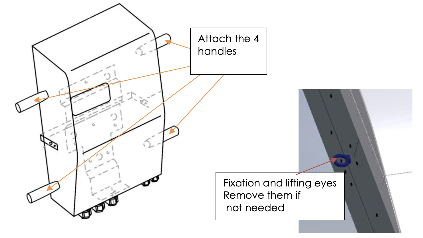
2 removable handles on each side of the device can be screwed to help the lifting of the device and then leave adequate space for them. Never lift the device by handling the plastic cover part! If the next3 is installed in a closed cabinet, it must have a sufficient ventilation to guarantee that the ambient temperature is kept within the operating limits of the next3.
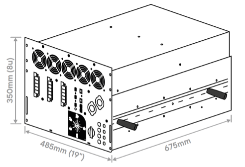
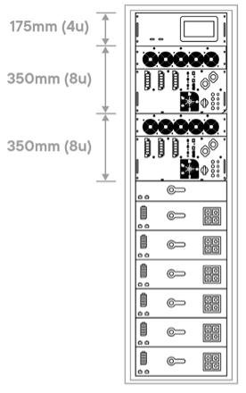
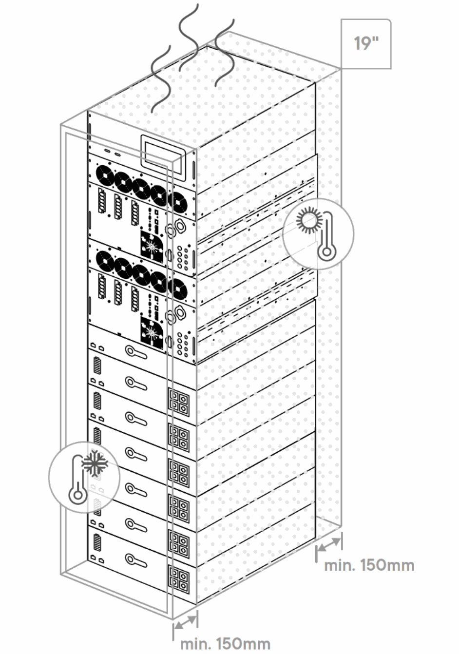
Dimensions of the 19" rack next3
The rack version of the next3 is for 19” rack and has the equivalent of 8 units in height.
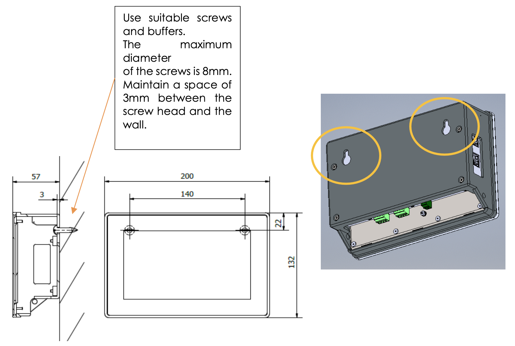
Dimensions of the nx interface
The nx interface can be fixed on the inverter with a dedicated mounting frame or remotely wall-mounted. It can also be integrated into a control panel. See the mounting section for details of installation.
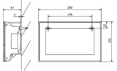
See the connections chapter for cabling of communication.
Unpacking
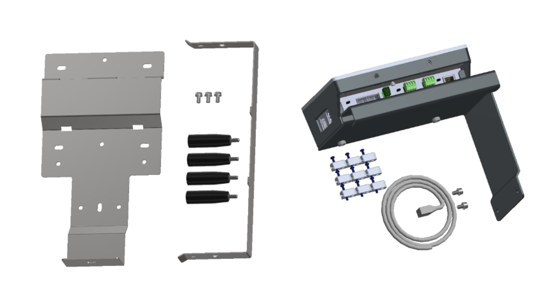
When unpacking, check that the next3 has not been damaged during transport and that all accessories listed below are present. Any fault must be immediately reported to the product distributor or the contact mentioned at the back of this manual. Check carefully the packaging as well as the next3.
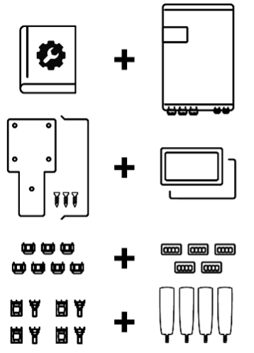
Contents:
- Quick Installation Guide and user interface guide
- Next3 inverter-charger
- Nx-interface with
-
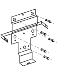
- Mounting structure
- USB stick with detailed technical manual, to be used for datalogging with the nx-interface.
- Kit for front panel fixing
- 1m communication cable
- Sunclix connectors for PV cables (4 pairs)
- Male connectors for
-
- CAN lithium battery communication
- RS485
- 2 pieces for AUX contacts
- 1 piece for CMD inputs
- Mounting plate (for wall mounted version) with 1 screw for fixing on the body of the next3. The screws for the wall are not provided. Choose the appropriate screws for your wall.
- Fixing belt with 2 screws
- 4 handles
- Cable-glands for battery and AC (for wall mounted version)
Mounting place
Next3 is designed for indoor use (IP30) and the place of installation must satisfy the following criteria:
- Protected from any unauthorised person
- Protected from water, dust and in a place with no condensation
- It must not be situated directly above vented lead acid batteries, or in a cabinet with them, due to corrosive gas
- No easily inflammable material should be placed directly underneath or close to the next3
- Ventilation holes must always remain clear and be at least 20cm from any obstacle that may affect the ventilation of the equipment (see mounting schematics)
- In mobile applications, it is important to select an installation site that ensures the lowest possible vibration level
- According to the IEC/EN 62109-1 standard, the level of pollution at the mounting place should not exceed PD2 (second-degree environment), which means that there can be pollution as long as it becomes not electrically conductive
- Protected from direct solar radiation or heat sources
As much as possible, reduce exposure to sudden temperature variations: important heat variation may create undesired and harmful condensation inside the equipment.
Unpacking and mounting process of the wall mounted next3
- Unscrew the 8 screws situated on the side of the casing
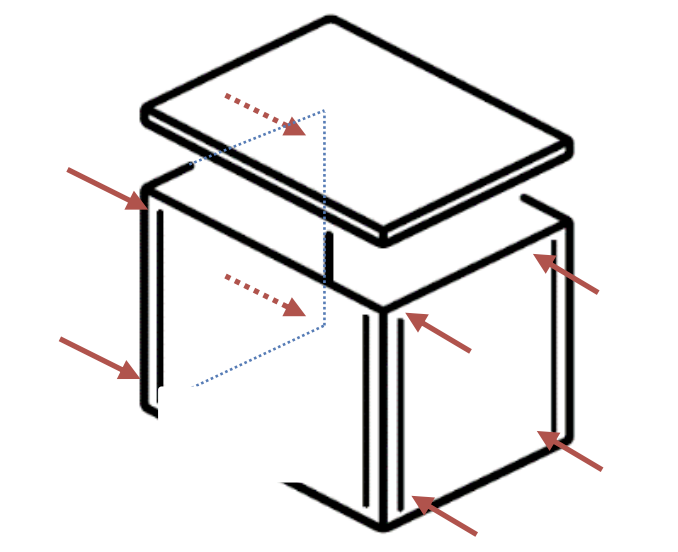
- Remove top cover
- Take the manual, the fixation structure, check the content
- Remove the external casing
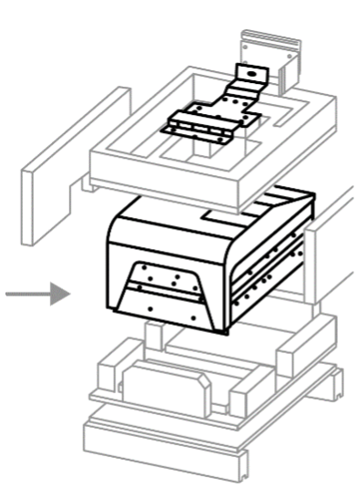
- Cut the strings maintaining the next3 to the bottom of the casing
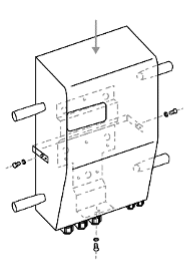
- Fix the 4 handles on the two sides of the next3 and remove the loops if you don't need them to move the next3.
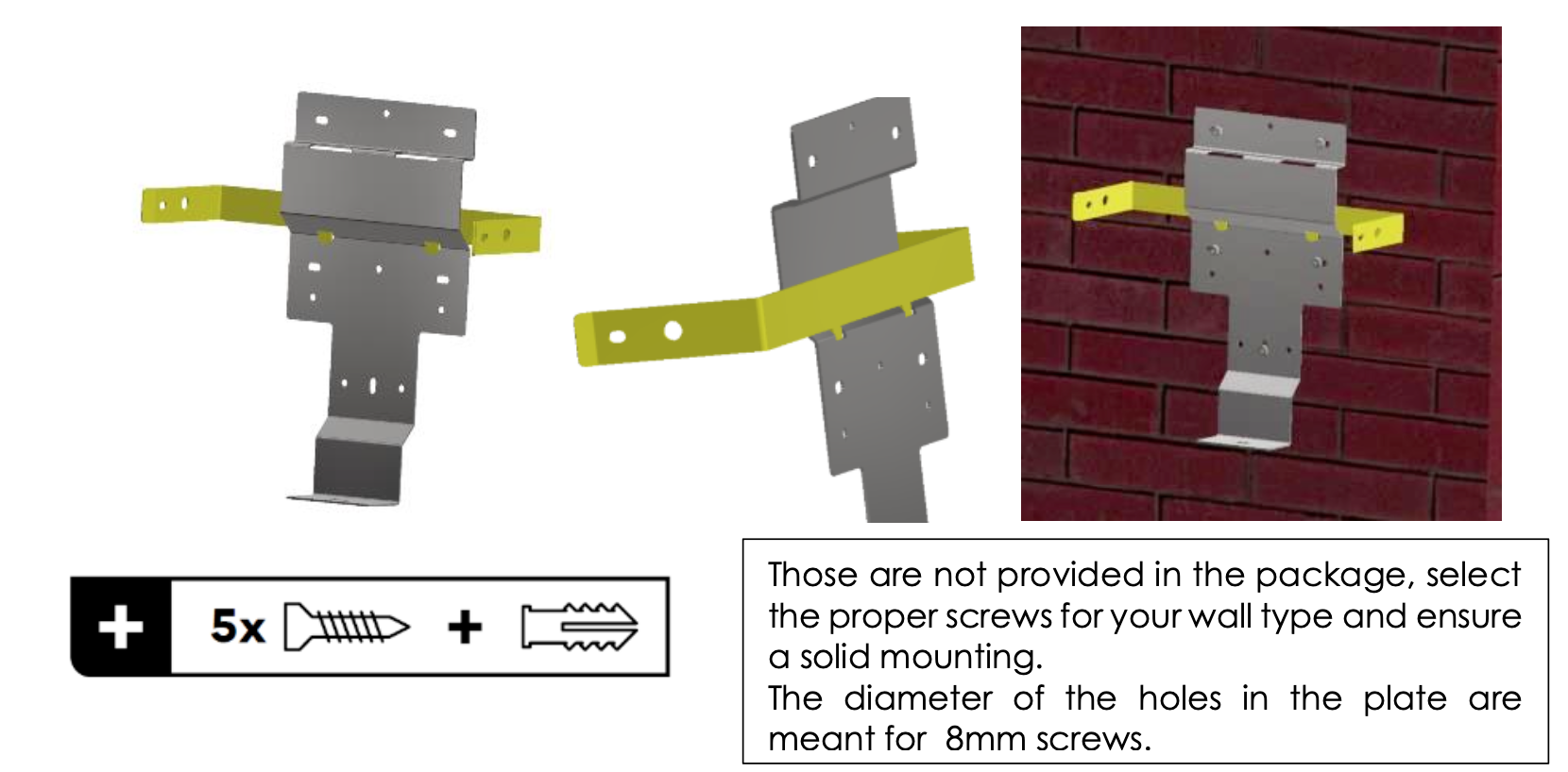
- Fix the mounting plate on the wall, leaving enough space around the unit for the ventilation and cabling. The next3 must be installed on a non-flammable wall or support. Don’t forget to put the fixing-belt in place before screwing the mounting plate on the wall:
In vehicles (road or marine), or when the support undergoes significant vibrations, the next3 is to be mounted on anti-vibration elements. The fixing belt use is mandatory in those cases.
For the wall mounting plate, use the 5 screws and buffers capable to stand the weight of the inverter in full safety.
When drilling the holes, keep at least 542mm from the top screws to the ceiling to respect the 250mm clearance above the device.
Keep at least 290mm to the nearest on the left wall (150mm+454mm/2- 90mm=287mm) and 350mm to the next next3 (120mm+454mm/2=347); distance from the middle of the plate.
Keep sufficient space below for the cabling.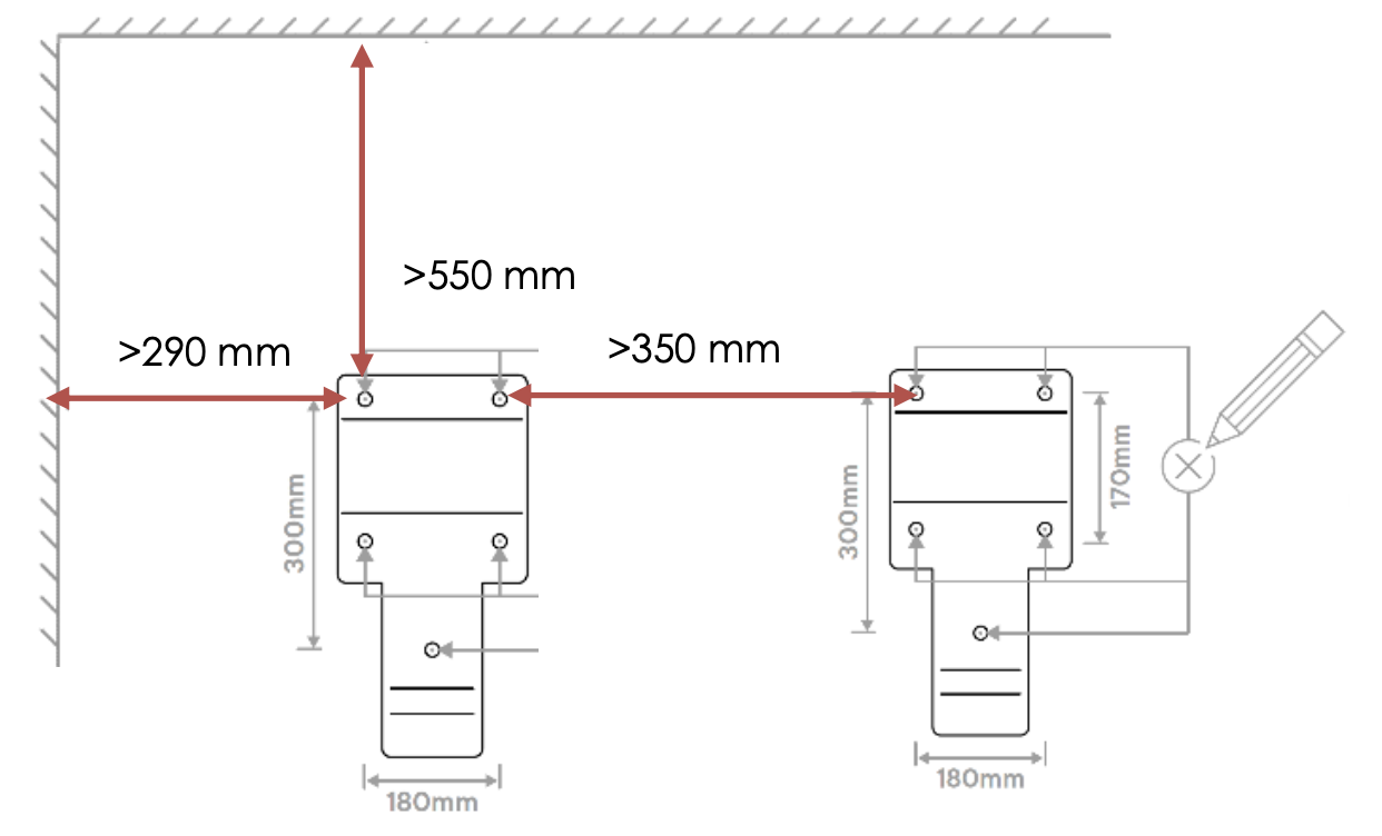
Attention: The next is a heavy equipment (~60kg) and must be mounted to a support/structure designed to bear such a load. It is imperative to ensure a complete and safe fastening of the equipment. If simply hung, it may fall down and cause severe damages.
For the next steps there must be 2 people at least! - Hang the next3 on the structure
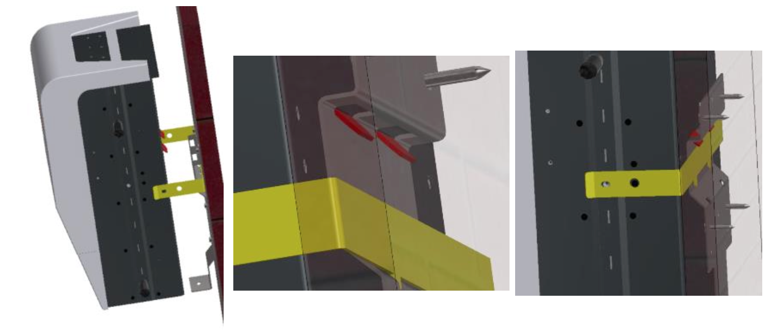
- Fix the structure at the bottom with the provided screw
- Fix the belt on the sides with the screws provided
- Fix the nx interface with 2 screws provided. Install the communication cable on the screen before mounting.
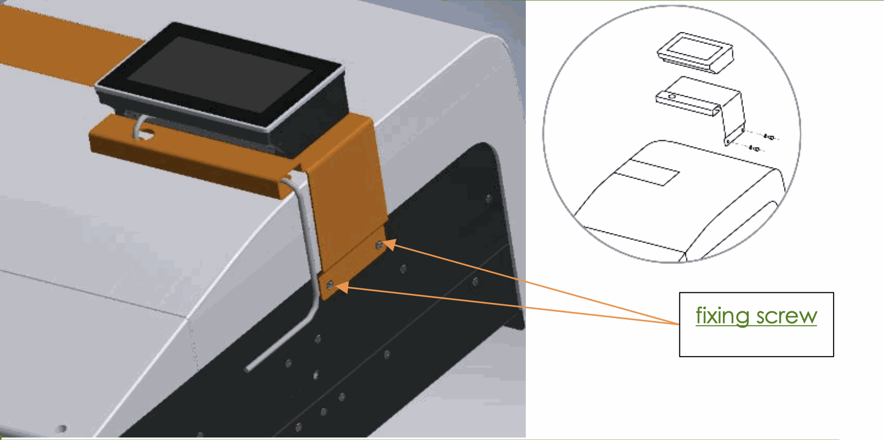
The nx-communication cable goes in the plug on the left of the nx interface and is easier to install before the mounting on the nx device. The ethernet cable (LAN) goes on the right.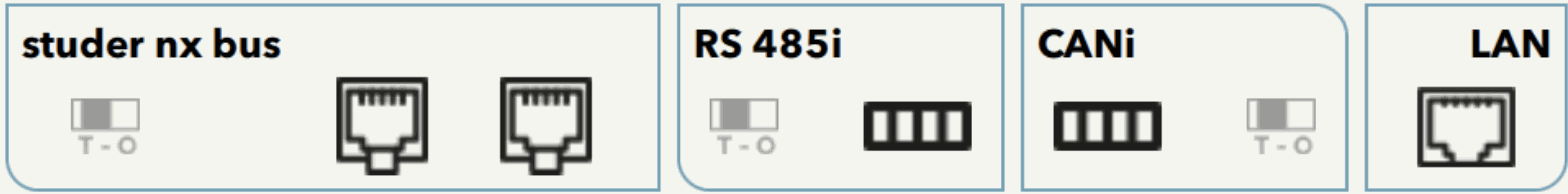
See the connection sections for details.
Special installation on the wall or in a cabinet is shown in the following chapter below. - Open the bottom panel and proceed with wiring.
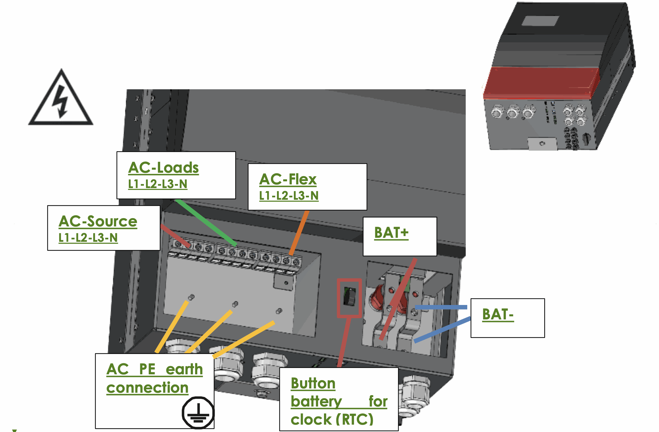
Go to the connections section of this manual for all explanations about electrical connections.
Unpacking and mounting process of the next3 rack
The first steps of the unpacking of the rack version is similar to the wall mounted version. The same packaging is used.
The mounting in cabinet must be performed leaving sufficient space in front and behind the units. If a closed cabinet is used, some extraction fans must be used to evacuation the heat of the power conversion losses.
Go the connections section of this manual for all explanations about electrical connections.
Nx interface wall mounting
The nx-interface can be hanged on a wall with two screws. The head of the screw goes in the dedicated slot on the back of the nx-interface.
The nx interface is supplied with a 1m communication cable to mount on the device.
Cables of different lengths (3m, 10m and 50m) can be ordered. Item reference is: nx- ethernetCab 3m/10m/50m. The length in meters is specified in reference.
You can buy your own ethernet cable for communication; it must be ethernet cat5 with 26AWG.
The maximal distance between the inverter and the nx-interface depends then on the rest of the cabling. The total communication cable length in one system for the Studer-nx-bus is 75m.
Nx interface rack panel mounting
The nx-interface can be integrated in a panel. The maximum thickness of the panel cannot exceed 4mm.
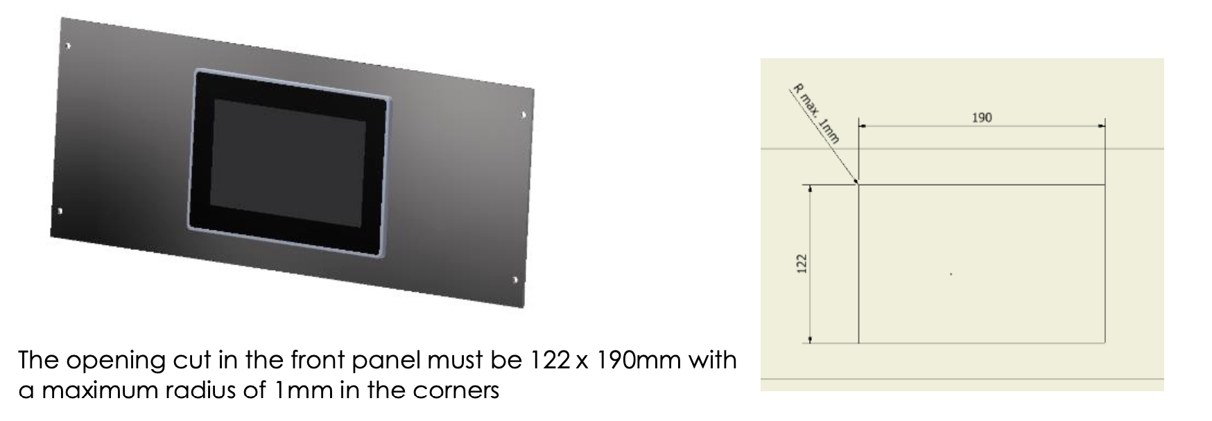
Mounting instructions:
- Insert the device from the front into the cut-out of the panel and push it carefully until it is fully inserted.
-
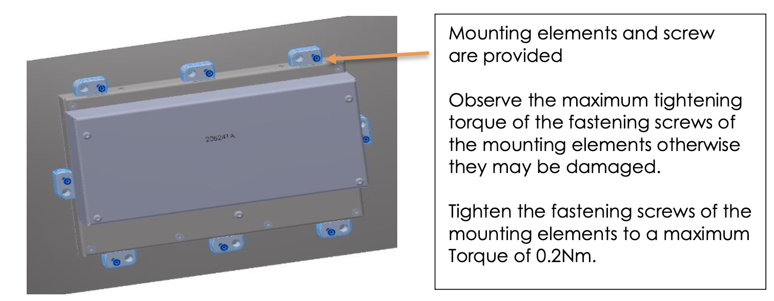
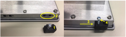
- Insert the mounting elements (1) into the provided lateral T cut-outs (2) and push them sideways (3) so that they are locked.
-
For the first mounting elements in a corner, tighten the fixing screw (4)until it presses on the plate. Tighten the fastening screws to a maximum torque of 0.2 Nm.
- Repeat procedure 3 for opposite mouting element.
- Repeat procedure 3 for remaining mounting elements.